
Summary of Build a transistor circuit board for controlling Air Conditioner remote control with Arduino
Concise summary: Students struggled to control an A/C with Arduino using recorded IR codes or by modding original remotes. They succeeded by hacking a universal A/C remote: identifying button contact lines, soldering header pins, and driving those lines via NPN transistors from Arduino—avoiding relays and preserving original remotes. The guide lists required tools, explains opening the remote, locating button traces/colors, and preparing a transistor-based interface to control many A/C brands.
Parts used in the Universal A/C remote hack:
- Universal A/C remote control (supports many manufacturer types)
- Arduino microcontroller
- Clamps and holders
- Soldering iron set
- Pliers (long and cutter)
- Scalpel blade
- Jumper wires
- Resistors (22K used)
- NPN transistors (any kind)
- Pin strips and headers
- Multimeter
- PCB board (stripboard)
- Marker pen
- Drill set and attachments
- Drill holder (optional)
- Screwdrivers or plastic opening tools
- Tape
- Soft sponge tape
I was supporting a group of student on their graduation project. One of the difficulties they faced was on controlling an A/C unit with Arduino microcontroller.
The first experiment we tried to work it out was by record the A/C remote control beam signal for each needed button by using the IRrecvDump code with IRremote library for Arduino (https://github.com/shirriff/Arduino-IRremote). Then, use these signals to send it to the A/C unit directly. The main problem we faced was on analyzing the ON/OFF signal code. The ON/OFF signal code curries more than one signal code. This includes switch signal + fan speed + thermostat degree. Some times this could include the conditioning mode, as well, such as Dray, Cool, Fan etc. Basically, this was unsuccessful method to work with all A/C remote controls.
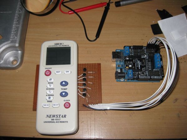
The second experiment was by hacking the remote control by adding a sort of wires then attached to Arduino over a relay. Modern remote controls are quite sophisticated and not easy to hack. One mistake in soldering could cause fail of that remote. So, it was too risky to hack and modify the original A/C remote control. However, we did some soldering test on unused remote control until we succeed. Then we wire it up to a number of relay module to control it with Arduino. But relay is quite expensive so that we needed to do a cheap hack without spending much money. Also we want to use less wires to be attached to Arduino to get extra space to add more features.
After first and second experiments we come up with a successful way to control the A/C unit. In this experiment, we got rid of using relay also we didn’t need to risk our original remote control. So that, we put our hand on a Universal A/C remote control. Then do some hack to that remote to control the A/C through Arduino interface. This will give us a chance to control different type of A/C. The one we hacked is capable to control 1000 A/C manufacturer type.
Step 1: Gathering tools
First of all, you will need to prepare some tools. I’m using:
* Clamps and holders: this helps me to hold the circuit board while soldering.
* Soldering iron set.
* pliers (long & cutter).
* Scalpel blade: I use it to unseal the protective layer over the copper in the A/C remote control, to make it easy to solder a wire to it.
* Jumper wires: a suitable one to connected to Arduino board.
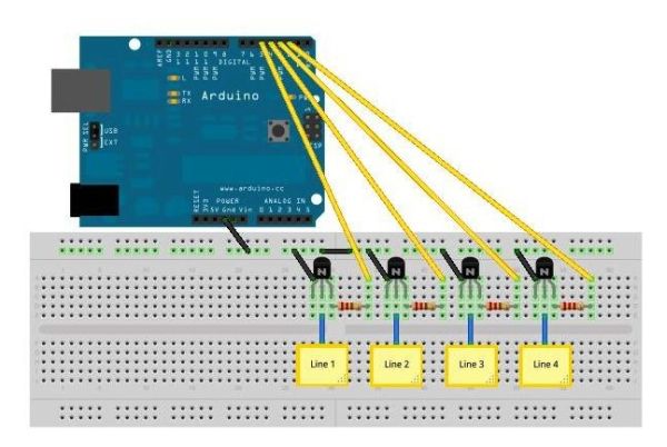
* resistors: I’m using 22K to protect the NPN transistor from overheating and/or damage.
* NPN transistors: any kind of NPN. Use the multimeter to figure out the E B C pins.
* Pins strip & its headers: those are goes to the base and remote control for the interaction.
* Multimeter: I use it for double check the wiring and for finding the NPN transistor pins.
* PCB board: I’m using stripboard type. It is easy to deal with, also, less soldering.
* Marker pen: It used to identify parts on circuit board.
* Drill set with its attachment: I use it for drilling hols into PCB boards. Also for cutting the back cover of the remote control for header pins.
* Drill holder (optional).
* Some screwdriver: for removing the remote control back cover. I’m using a plastic tool kit (that uses with mobile phones), it leaves no scratch on the remote body.
* Tape: I use it for holding the remote control LCD screen and protect it.
* A soft sponge tape: I use it to protect the back of the board base from any direct contact. Also for leveling remote on base.
This is a bit tricky step. First you have to use a screwdriver (screwdriver plastic) to open the remote control chest. Then, you will need to identify both lines for each button.
Some remote controls has a common line for all buttons (see this http://tronixstuff.files.wordpress.com/2011/04/remotepcbss.jpg). This is too easy to hack.
Mostly, modern remote controllers has complicated set of lines. Which could has a shared line that can be common and main (signal) sequentially with each other.
In this step, I identified each combined line with different colors.
From the picture, you will notice that each button has two different colors (e.g. to press on ON/OFF button we have to contact the Red & purple lines).
Also, because I’m using this remote with Arduino, I discard the use of the buttons on bottom, which they set the timing and manage the Air Conditioner to start or stop on a specified time. As this can be easily programmed with Arduino it self. These buttons are identified with color GRAY, which is the common line. So I didn’t take it into account.
The final colors combination are PURPLE, RED, BROWN, GREEN, BLUE and YELLOW.
Next step, we will included the header pins to the A/C remote control board.
NOTE THAT YOU CAN USE ANY UNUSED PLASTIC BUSINESS CARD TO OPEN THE REMOTE CHEST SAFELY.
* Soldering iron set.
* pliers
* Scalpel blade
* Jumper wires
For more detail: Build a transistor circuit board for controlling Air Conditioner remote control with Arduino
- How did they attempt to control the A/C initially?
They recorded IR remote signals using IRrecvDump and tried to resend them from Arduino, but ON/OFF codes included multiple combined settings and this was unsuccessful. - Can you hack the original A/C remote to control it with Arduino?
Yes, but modern remotes are sophisticated and soldering mistakes can damage them, so it was risky; they tested on unused remotes first. - What successful approach did they use instead of relays?
They hacked a universal A/C remote and interfaced it to Arduino using NPN transistors and header pins, avoiding relays and original remote risk. - Why use a universal A/C remote?
Because it can control up to 1000 A/C manufacturer types, allowing broader compatibility without modifying original remotes. - What tools are needed to hack the remote?
Clamps and holders, soldering iron, pliers, scalpel blade, jumper wires, resistors, NPN transistors, pin headers, multimeter, stripboard, marker, drill set, screwdrivers, tape, and sponge tape. - How do you identify button lines on the remote PCB?
Open the remote, inspect the PCB traces, and identify contact line pairs for each button; the example used colored lines like purple, red, brown, green, blue, and yellow. - Do some remotes have a common line for all buttons?
Yes, some remotes have a common line for all buttons, which is easier to hack; modern remotes often have more complex shared or sequential lines. - What resistor value was used to protect the transistor?
They used 22K resistors to protect the NPN transistor from overheating or damage. - How did they protect the remote during modification?
They used tape to protect the LCD, soft sponge tape to protect and level the board base, and plastic opening tools to avoid scratching the remote body.
