Summary of Arduino Projects on a breadboard (no serial com)
This article guides users in creating a standalone Arduino-compatible circuit on a breadboard using an ATmega328 chip, eliminating the need to purchase multiple Uno boards for non-serial projects. The process involves wiring a 9V power supply, installing an LM7805 voltage regulator, and connecting essential components like capacitors, resistors, LEDs, and a crystal oscillator to replicate the functionality of an Arduino Uno directly on a prototyping board.
Parts used in Arduino Projects on a breadboard (no serial com):
- Arduino Uno & USB cord
- Wire Strippers & Leatherman
- Solder & Soldering Iron
- 22 AWG Wire
- Breadboard
- LM7805 Voltage Regulator
- 16 Mhz Crystal
- Push Button
- 220 Ohm Resistor (2x)
- 10K Ohm Resistor
- 22 pF Capacitor (2x)
- 10 uF Capacitor (2x)
- Green LED
- Red LED
- ATmega328 (with Bootloader)
- 9V DC power Supply
Intro:
If you’ve got an Arduino Uno and want to start duplicating projects without having to buy an Uno every time… get ready to live! This instructable will show you how to move your projects (that do not require serial communication) onto a breadboard for prototyping or expansion. If you’re looking for a more permanent solution check out these (breadboard ) (options ).
Stuff You Should Have Already:
-Arduino Uno & USB cord: You’re gonna need this to program the new ATmega328
-Wire Strippers & Leatherman: A must have for wire management
-Solder & Soldering Iron: Great for sticking stuff to other stuff
-22 AWG Wire: Makes this project really difficult if you don’t have it
Stuff To Buy:
Breadboard ……………………………..1x $ 8.00
LM7805 ……………………………………1x $ 0.50
16 Mhz Crystal ………………………… 1x $ 0.40
Push Button ……………………………..1x $ 0.11
220 Ohm Res …………………………. 2x $ 0.10
10K Ohm Res ………………………… 1x $ 0.05
22 pF Cap ……………………………….. 2x $ 0.12
10 uF Cap ……………………………….. 2x $ 0.10
Green LED ………………………………..1x $ 0.10
Red LED ………………………………….. 1x $ 0.09
ATmega328 (with Bootloader) ….1x $ 5.50
9V DC power Supply …………………1x $6.95 (get these for like $1 at thrift stores)
TOTAL ……………………………………….. $22.02
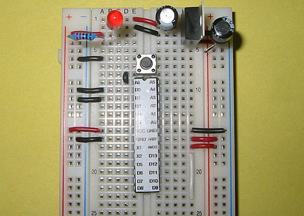
Step 1: The Power Supply
Step/Pic 1: Wire up the bottom of your board so that you will have power on both side rails
Step/Pic 2: Pop these little pieces of wire in, the tags will show you whats coming next
Step/Pic 3: Install your hardware, here are some things to note: the cathode (long leg) of the LED gets plugged into power. Unlike resistors, aluminum electrolytic capacitors have a positive and a negative lead. The leg with the gray strip above it means it is GND, and the longer leg is positive.
-A 10 uF capacitor needs to be tied to PWR and GND before and after the voltage regulator. Make sure the long wire goes to power, and the gray lead goes to GND.
-The LM7805 will straddle the 3 power lines; 9V DC in at the top (pin 1), GND at the middle (pin 2), and 5V DC out at the bottom (pin 3).
-Make sure your resistor is in series with the LED, it keeps the current through the LED from getting too high.
Step/Pic 4: Cut off the plug on the power supply, and solder on a little colored 22 AWG on the ends. The wire with the white strip on it will be PWR, the other is GND.
DANGER! make sure these two leads never touch while the power supply is in your wall. It will probably explode and catch fire, and will definitely burn up your power supply.
Step 5: Once you’re sure everything is hooked up correctly, plug in your power supply and your little LED should light up (this is what we want)
For more detail: Arduino Projects on a breadboard (no serial com)
- How do I wire the bottom of the breadboard?
You must wire up the bottom of your board so that you will have power on both side rails. - Which leg of the capacitor connects to GND?
The leg with the gray strip above it means it is GND. - What are the pin functions of the LM7805?
Pin 1 is 9V DC in at the top, Pin 2 is GND at the middle, and Pin 3 is 5V DC out at the bottom. - How should the capacitor be positioned relative to the voltage regulator?
A 10 uF capacitor needs to be tied to PWR and GND before and after the voltage regulator. - Why is a resistor needed in series with the LED?
It keeps the current through the LED from getting too high. - What color indicates the positive wire on the power supply?
The wire with the white strip on it will be PWR. - What happens if the two leads of the power supply touch while plugged in?
It will probably explode and catch fire, and will definitely burn up your power supply. - Does this project require serial communication?
No, this method is specifically for projects that do not require serial communication.