a.k.a. the gratuitously complicated bidirectionally communicating Arduino-based scrolling Twitter display and notifier.
—-
This project was mainly done as an excuse to learn how to use character LCD displays with my Arduino, and figure out how to make a bidirectional serial protocol. One major design goal was that the hardware would take user input and communicate back to the PC, not just run as a “dumb” display being driven entirely by the computer. This allows the Arduino to have a physical scrolling speed control which affects the script running on the PC.
Features:
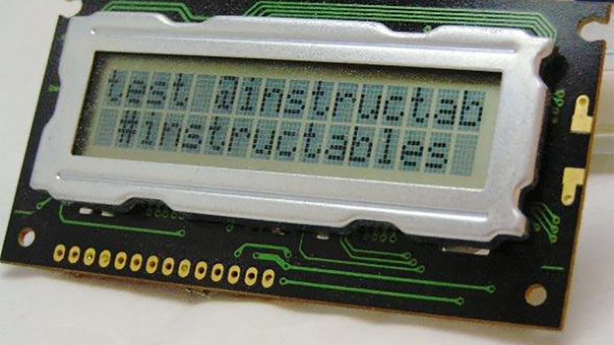
– 16 x 2 character LCD displaying scrolling tweets from a chosen feed or search term
– Servo-operated flag raises when there are unread tweets (with no Arduino servo twitch!)
– Speed control dial adjusts scroll speed
– It’s got Electrolytes
Step 1: System architecture
A rather grandiose title that essentially means “breaking the design into parts”, as this is quite a complex thing.
Hardware:
The hardware forms the Arduino’s interface with the real world. The hardware consists of a two-line character LCD for displaying messages, a speed control that lets uers change the scrolling speed while the device is running, and a servo-operated flag that raises when the script detects there are unread tweets.
Firmware:
The sketch running on the Arduino runs a loop doing two main actions. It sends a “status” request to the script running on the server PC and awaits a response containing the number of tweets in the list, and whether there are any unread. It then sends a “message” request, gets the text of a tweet, and displays it scrolling across the display. It reads the potentiometer in real time to get the desired scroll speed, and raises and lowers the flag to notify of new tweets.
Software:
The server software maintains a list of all tweets seen since it started running. When the script receives a “status” request it replies with the number of tweets it currently has in the list, and whether there are any unread tweets. When it receives a “message” request the script sends the next tweet in the list, returning to the beginning of the list either when it reaches the end of the list or when it finds new tweets.
The script also has to keep the list of tweets up to date by checking the Twitter API to get the latest messages. This is also timed to occur at most once every three minutes: when the script receives a “status” request, if more than three minutes have elapsed since the last check, it gets the list of tweets and checks to see whether there are any unread.
Step 2: Hardware
Wiring instructions
Display:
For a serial 16×2 character LCD:
Pin 1. Ground
Pin 2. VCC (+5V)
Pin 3. Contrast
Pin 4. Register Select (RS)
Pin 5. Read/Write (R/W)
Pin 6. Clock
Pin 7. N/A
Pin 8. N/A
Pin 9. N/A
Pin 10. N/A
Pin 11. Bit 4
Pin 12. Bit 5
Pin 13. Bit 6
Pin 14. Bit 7
Pin 15. Backlight Anode (+)
Pin 16. Backlight Cathode (-)
You can find out more about those at the Wikipedia page about this series of character LCDs.
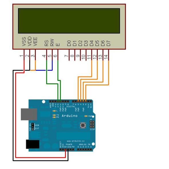
To wire the LCD to the Arduino, connect the following pin numbers on the LCD:
1: GND
2: +ve (+5V)
3: GND*
4: Arduino pin 12
5: GND+
6: Arduino pin 11
11, 12, 13, 14: Arduino 5, 4, 3, 2
*: Pin 3 should technically be connected to a 10K potentiometer between VCC and GND, however my display had a good contrast at the bottom of the potentiometer’s range so I just tied the contrast line to ground. Also, I wanted the potentiometer for something else 🙂
+: Pin 5 switches the LCD between read and write mode, but we never need to read from the LCD so hold this to ground to keep the display in write mode.
Optional: speed control
Potentiometer GND: GND
Potentiometer VCC: VCC
Potentiometer wiper: Arduino analog in 0
Optional: “new tweet” flag
You will need a transistor and servo.
Transistor emitter: GND
Transistor base: Arduino pin 7
Transistor collector: servo GND
Servo VCC: VCC
Servo control: Arduino pin 9 (PWM)
If you want to use the servo, make sure you have your Arduino plugged into an external power supply (USB won’t provide enough juice) and put the electrolytic capacitor across the power rails to provide spike current.
Transistor base: Arduino pin 7
Transistor collector: servo GND
For more detail: Arduino LCD Twitter display