Summary of Arduino Bluetooth Camera
This article details a project enabling bidirectional image transfer between an Android phone and an Arduino UNO via Bluetooth. By offloading heavy data processing to a specialized TFT shield, the system captures images from an OV7670 camera on the Arduino and displays them on the shield or sends them to the phone. Conversely, it can receive images from the phone's camera and display them on the TFT screen. The setup utilizes a custom Android application and requires specific software libraries and power configurations for stable operation.
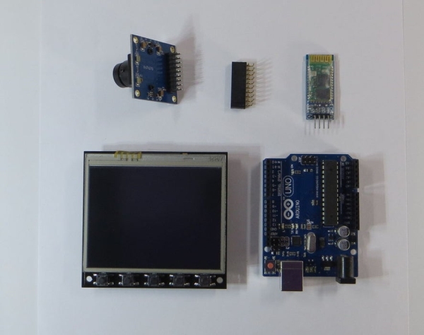
Parts used in the Arduino Bluetooth Camera Project:
- Arduino UNO
- Unique TFT shield (3.5 inch, 320x240 resolution)
- AC-DC power adapter (6-12 volt, >600mA)
- Camera module OV7670
- Bluetooth module HC-06 or HC-05
- Android phone
- Library for Unique TFT shield
- APK file for Android phone (ArduinoTFT.apk)
Today you can hardly surprise anyone with a mobile phone with a camera, wireless gadgets and other technical advances. Thanks to the Arduino platform, millions of people have discovered the wonderful world of electronics and programming. 100,500 instructions were written on how to exchange data between a mobile phone and Arduino via bluetooth … What am I talking about? Yes. I want to exchange data between a mobile phone on Android and Arduino UNO through bluetooth in 100,501 times. But I want to transmit not just a set of characters and numbers, but pictures.
Someone will say that this is impossible, Arduino is too slow to process large amounts of data with good speed. And he will be absolutely right. And what if a little bit of help Arduino – to transfer all the “hard” work on the shoulders of other device? And there is such a device!
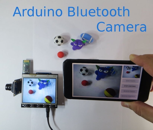
This is a unique TFT shield for Arduino. Information about this logo is in these articles: article 1, article 2. In this instructables, I will demonstrate how you can connect via bluetooth between Arduino and Android phone, get a picture from the OV7670 camera on Arduino UNO and transfer it to Android phone. Then, on the contrary, transfer the picture (image from the camera) from the Android phone to Arduino UNO and display it on the screen of a unique TFT shield.
A special application was written for the Android phone.
Brief characteristics of TFT shield:
- Size 3.5 ” diagonal,
- Resolution 320×240,
- Number of colors 65536 (16-bit),
- Resistive touch screen (XPT2046 controller),
- 5 buttons,
- RTC IC DS1307 with 3V lithium battery CR1220,
- Slot for connecting a micro SD card,
- 4-pin (2.54 mm) connector for connecting the Bluetooth module HC-05 (-06), ESP8286 WiFi module.
- 20-pin (2.54 mm) connector for camera (OV7670).
Step 1: List of Components Needed
Hardware:
- Arduino UNO;
- Unique TFT shield;
- AC-DC power adapter 6-12 volt, >600mA;
- Camera OV7670;
- Bluetooth module HC-06 (HC-05);
- Android phone.
Attention: It is necessary (!) To use a 6-12 volt power adapter to operate the TFT shield, because the maximum current of 500 mA from USB is not enough for normal operation.
Software:
- Arduino IDE;
- Library for Unique TFT shield;
- APK file for Android phone.
Step 2: Preparing
Software
All demonstration sketches are written in the Arduino IDE environment, therefore at the beginning it is necessary to install the Arduino IDE – https://www.arduino.cc/en/main/software.
Then you need to install a library for TFT shield – github.com/YATFT/YATFT (download the library and unpack it into the “libraries” folder in the Arduino IDE directory).
After installing the Arduino IDE, you must program the Arduino UNO board. For simplicity, I recommend flashing it separately, without TFT shield. For this:
- Connect the USB cable to the Arduino UNO board;
- Run the Arduino IDE on the computer;
- Select the corresponding port to which the Arduino UNO is connected;
- Download the ArduinoBluetoothCamera.ino demo sketch (and file ov7670_regs.h for camera init);
- Click the button Upload.
If the Arduino UNO board is successfully programmed, you can proceed to the next step.
Android
On the Android phone, you need to install the ArduinoTFT.apk. Allow the app to use the Bluetooth and Camera.
Bluetooth module
It is necessary to set the exchange rate in the Bluetooth module to be 115200 (command “AT+UART=115200,0,0”). This is the optimal speed at which Arduino UNO manages to receive and process data. (Theoretically, you can increase the speed, optimize data reception and processing, but this requires a larger amount of RAM).
More detailed instructions on how to set the exchange rate can be found on the Internet, for example, here: https://www.instructables.com/id/Communication-Bluetooth-Module-With-HC-05-HC-06/ .
(!) Please note that the Bluetooth module connects to the debug port of Arduino UNO. Thus, when working with bluetooth, the debug port is not available. And before programming the Arduino UNO (complete with the Bluetooth module) must disconnect the Bluetooth module. And after programming, set it back (!)
Step 3: Assembly
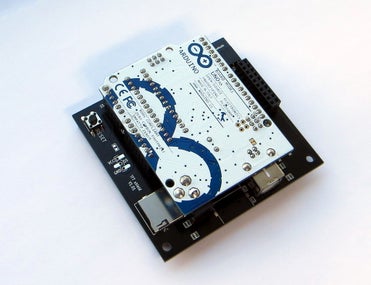
Assembly of the device is quite simple:
- Connect together Arduino UNO and TFT-shield;
- Connect the OV7670 camera to the 20-pin connector on the TFT-shield of the shield (sometimes I use an angled 18-20 pin connector with a 2.54 mm pitch as an adapter);
- Connect the Bluetooth module HC-06 (HC-05) to the 4-pin connector with the words “Bluetooth” on the TFT-shield;
- Connect the 6-12V power adapter to the power input on the Arduino UNO board.
After turning on the power, the TFT shield’s screen should turn red. This means the willingness to receive commands from the Android phone.
Step 4: Demonstration
Perform the following operations on the Android phone:
- Launch the ArduinoTFT application on the Android phone;
- Turn the phone in a horizontal position;
- Enable the Bluetooth connection, select the detected Bluetooth module (HC-06);
Two windows and four buttons should appear on the screen:
- The top right window is the phone’s camera viewfinder window;
- Large left window – received or sent images.
Button functions:
- Transfer single image from Android phone to Arduino;
- Continuous transfer of images from the Android phone to Arduino;
- Transfer single image from Arduino to Android phone;
- Continuous transfer of images from Arduino to Android phone.
The image size is 320×240 pixels (2-5 kB). This chapter has a demo video.
If you like my instructable, I would appreciate an assessment. Perhaps this will give me motivation for new instructables 🙂
Thanks for attention!
Source: Arduino Bluetooth Camera
- How do I power the TFT shield properly?
You must use a 6-12 volt power adapter with over 600mA current because the USB port cannot supply enough power. - What is the optimal Bluetooth exchange rate for this project?
The exchange rate should be set to 115200 baud for optimal data reception and processing speed. - Can I connect the Bluetooth module while programming the Arduino?
No, you must disconnect the Bluetooth module before programming the Arduino UNO as it connects to the debug port. - What library is required for the TFT shield?
You need to install the YATFT library from github.com/YATFT/YATFT into your Arduino IDE libraries folder. - How do I control the image transfer direction?
The Android app provides four buttons to transfer single or continuous images in both directions between the phone and Arduino. - What are the dimensions of the transferred images?
The image size is fixed at 320x240 pixels, which equals approximately 2-5 kB. - Which camera module is used in this setup?
The project uses the OV7670 camera connected to the 20-pin connector on the TFT shield. - What happens when the device powers on successfully?
The TFT shield screen turns red, indicating it is ready to receive commands from the Android phone.