A Rotary encoder is an input device which helps the user to interact with a system. It looks more like a Radio potentiometer but it outputs a train of pulses which makes its application unique. When the knob of the Encoder is rotated it rotates in form of small steps which helps it to be used for stepper/Servo motor controlling, navigating through a sequence of menu and Increasing/decreasing the value of a number and much more.
In this article we will learn about the different types of Rotary Encoders and how it work. We will also interface it with Arduino and control the value of an integer by rotating the Encoder and display its value on a 16*2 LCD screen. At the end of this tutorial you will be comfortable with using an Rotary Encoder for your projects. So let’s get started…
Materials Required
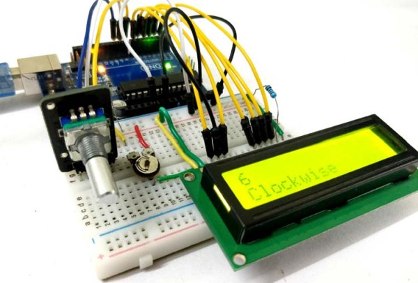
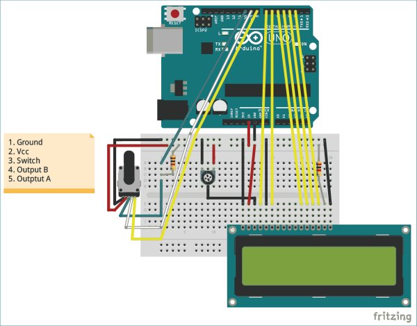
- Rotary Encoder (KY-040)
- Arduino UNO
- 16*2 Alphanumeric LCD
- Potentiometer 10k
- Breadboard
- Connecting wires
How does a Rotary Encoder Work?
A Rotary Encoder is an electromechanical transducer, meaning it converts mechanical movements into electronic pulses. It consists of a knob which when rotates will move step by step and produce a sequence of pulse trains with pre-defined width for each step. There are many types of Encoders each with its own working mechanism, we will learn about the types later but for now let us concentrate only on the KY040 Incremental Encoder since we are using it for our tutorial.
The internal mechanical structure for the Encoder is shown below. It basically consists of a circular disc (grey colour) with conductive pads (copper colour) placed on top of this circular disc. These conductive pads are placed at an equal distance as shown below. The Output pins are fixed on top of this circular disc, in such a way that when the knob is rotates the conductive pads get in contact with the output pins. Here there are two output pin, Output A and Output B as shown in the figure below.
The output waveform produced by the Output pin A and Output B is show in blue and green colour respectively. When the conductive pad is directly under the pin it goes high resulting it on time and when the conductive pad moves away the pin goes low resulting in off time of the waveform shown above. Now, if we count the number of pulses we will be able to determine how many steps the Encoder has been moved.
Now the question may arise that, why do we need two pulse signals when one is enough to count the number of steps taken while rotating the knob. This is because we need to identify in which direction the knob has been rotated. If you take a look at the two pulses you can notice that they both are 90° out of phase. Hence when the knob is rotated clockwise the Output A will go high first and when the knob is rotated anti-clockwise the Output B will go high first.
Read more: What is Rotary Encoder and How to Use It with Arduino