This project demonstrates building a real-time clock (RTC) with temperature display using an Arduino, DS3231 RTC chip, and SSD1306 OLED display (128×64 pixels).
The DS3231 RTC chip provides more accuracy than the DS1307 and incorporates an onboard temperature sensor. It maintains timekeeping even without the main power, making it well-suited for this application. It communicates with the microcontroller (Arduino in this case) via the I2C interface.
The DS3231 RTC and SSD1306 OLED share the same I2C bus but the microcontroller can only interact with one at a time depending on the address sent – 0x68 for the DS3231 and 0x3C for the SSD1306.
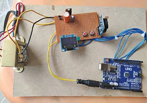
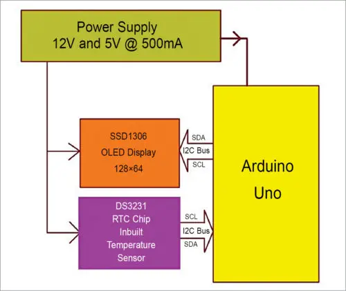
Figure 1 shows the author’s assembled prototype. Figure 2 provides a block diagram of the circuit, clarifying how the components interconnect and communicate.
Overall, this project demonstrates using commonly available I2C devices – a precise RTC chip and graphic OLED – to readout the time, date and internal temperature via an Arduino-driven display UI.
Circuit and working
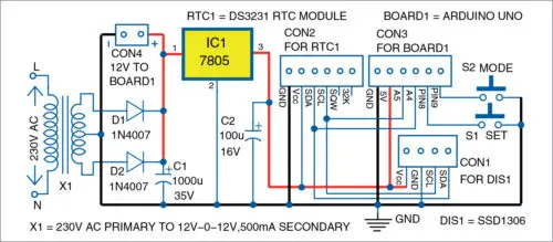
The circuit diagram in Figure 3 details the construction of the Arduino real-time clock with temperature readout.
At its core are the Arduino Uno microcontroller board (Board1) and DS3231 RTC module (RTC1). These communicate via the I2C interface.
Power regulation is provided by a 7805 5V voltage regulator IC (IC1) along with smoothing capacitors C1 and C2. This stabilized power allows operation of the 3.3V logic devices.
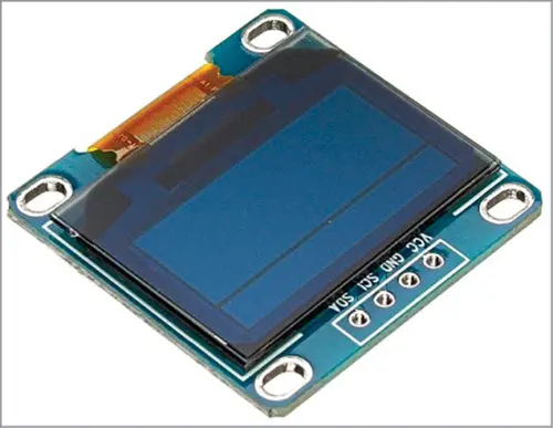
The 2.4cm OLED display (DIS1), an SSD1306 model, graphs the time/date/temperature information for the user. It connects to the I2C bus for data interaction.
A few passive components like pull-up resistors R1-R2 complete the interfacing between devices.
Overall, this diagram illustrates how commonly available ICs like the precise DS3231 RTC and graphic OLED panel are integrated via the Arduino’s microcontroller to build an I2C-based real-time clock with temperature visualization functionality.
SSD1306 OLED display
The OLED (organic light-emitting diode) display shown in Figure 4 is used in this project. OLEDs are thin, light-emitting panels that consist of organic thin films connected in series between two electric conductors.
Compared to traditional LCD displays, OLEDs offer improved image quality with full viewing angles and high brightness/contrast. They can produce a wider color gamut while requiring lower power.
Some key advantages of using this OLED model include its efficient and reliable operation. OLED technology provides better image quality and full visibility from any angle. It allows for higher luminosity with deeper blacks and richer colors versus LCD. Being lightweight and energy efficient, OLED is well-suited for portable and battery powered applications like this real-time clock project.
In summary, this OLED panel leverages the enhanced display attributes that OLED technology enables, making for a clearer and more vibrant visual interface compared to older display types.
LCD display modules are commonly found in electronic devices like computers, smartphones, game consoles, and televisions. They use liquid crystals to show text and images on a screen. These displays are widely available for purchase both in stores and online.
Connecting an LCD module to an Arduino board requires only a simple four wire interface. A pair of wires provides power, while another two wires handle data transfer using the I2C protocol. Also called two wire interface (TWI), I2C uses just two data lines to communicate between devices. This makes integrating an LCD very easy, with minimal wiring needed between the Arduino and display module.
DS3231 RTC module
The DS3231 module provides a low-cost and highly precise real-time clock solution. It tracks time down to the hour, minute and second, as well as the day, month and year. The module automatically accounts for leap years and months with less than 31 days.
The DS3231 can operate using either 3.3V or 5V power supplies, making it compatible with many microcontroller development boards. A common CR2032 3V battery powers the module, maintaining the time and date information for over a year. As seen in Figure 5, the DS3231 contains the clock crystal and battery connector on one side, and digital interface pins on the reverse. These features make it a suitable real-time clock component for a variety of projects.
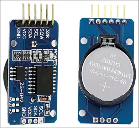
Connecting the DS3231 module to the Arduino board is simplified by the use of the I2C communication protocol. Only four pin connections are required:
VCC and GND pins provide power from the Arduino to the module. The SDA and SCL pins handle bidirectional data transfer using the I2C standard.
This two-wire interface streamlines the wiring between the devices. No additional pins are needed beyond the standard power and I2C signal lines. The DS3231’s I2C functionality makes integrating it with the Arduino board a straightforward process using just four basic connections.
Power supply
The regulated power supply circuit uses a full-wave rectifier and voltage regulation components to safely power the project devices. A step-down transformer (X1) converts the 230V AC household voltage to a 12V-0-12V secondary output. Diodes (D1 and D2) form the full-wave rectifier, rectifying the AC to DC. Capacitors (C1 and C2) filter the pulsating DC to produce a smooth DC voltage.
The 7805 voltage regulator IC (IC1) then regulates the DC voltage down to a stable 5V output. This 5V supply powers the DS3231 RTC module and the SSD1306 OLED display module. An additional 12V output from the rectifier circuit is used to power the Arduino Uno via its barrel power jack. Overall, the power supply circuit provides the necessary regulated voltages for the key project components in a safe, low-cost design.
Arduino Uno
At the core of the project is the Arduino Uno R3 development board. It features an ATmega328/ATmega328P microcontroller with 14 digital and 6 analog input/output pins. The board also includes 32KB of flash memory, a 16MHz crystal oscillator, USB connectivity, a power jack, ICSP header and reset button. Programming is done using the Arduino IDE software.
Two push buttons, S1 and S2, act as inputs to the Arduino. S1 is used for setting the time and date values stored on the RTC module. S2 toggles the Arduino through different display modes on the OLED screen.
The DS3231 Real Time Clock (RTC1) module and SSD1306 OLED display (DIS1) module both require a common ground connection to the Arduino board’s ground. This ensures the components can reliably communicate via the I2C protocol. Overall, the Arduino forms the central control unit that interfaces the input buttons to update the RTC, and displays the time/date data on the OLED screen.
Construction and testing
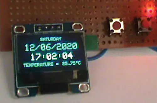
Once all connections are made, test the circuit functionality. Press and release the mode button (S2) – the cursor on the display will begin flashing in the day-of-week field.
Press and hold the set button (S1) to rapidly cycle through the days of the week, or press briefly to advance one setting at a time. Press and release S2 to move the cursor to the month. Here, press and hold S1 to quickly scroll months or press briefly to increment the month.
Press S2 again and the cursor will move to the date. As with the other fields, hold or briefly press S1 to change the date. The RTC chip automatically accounts for the correct number of days per month. Advance to the year field by pressing S2, then hold or briefly press S1 to set the year between 2000-2099, with leap years handled automatically.
Press S2 to set the hour, holding or briefly pressing S1 to increment. Only 24-hour time is used. Advance to minutes with S2 then use S1 to set. S2 moves the cursor to seconds, where S1 holds to freeze at zero or resets to zero on a brief press.
This synchronizes the time. The DS3231 also measures temperature, shown along with the date, time, and temperature readings on the display (see Fig. 6). Pressing S2 and S1 cycles through and updates each field as needed to set the correct time.
Software
The circuit operation is governed by software loaded onto the Arduino Uno’s internal memory. The main_code.ino program provides all necessary functions.
This program is written in the Arduino programming language and implements the project’s logic. The Arduino IDE version 1.8.11 environment compiles and uploads the sketch onto the Arduino board.
Once running on the microcontroller, the code dictates how the input buttons control the RTC time/date updating and display screen output. It integrates readings from the DS3231 module and drives the OLED display accordingly via I2C.
In summary, the Arduino software acts as the brain that orchestrates communication between the circuit components based on button inputs, allowing real-time clock functions and temperature display on the easy-to-read OLED screen.
Several header files are required to be included in the main_code.ino sketch to enable the necessary functionality.
The #include <Wire.h> header allows fast I2C communication with the two devices – the SSD1306 OLED display and DS3231 RTC module.
Graphics generation is made possible through #include <Adafruit_GFX.h>. This library permits shapes, inversions, symbols and .bmp images to be displayed.
Specific commands for the SSD1306 display are provided by #include <Adafruit_SSD1306.h>, allowing address mapping and alternating access to its eight pages of 128×64 pixels.
Additionally, two external Adafruit libraries must be imported into the Arduino IDE before compiling the code: Adafruit-GFX-Library-master.zip and Adafruit_SSD1306-master.zip.
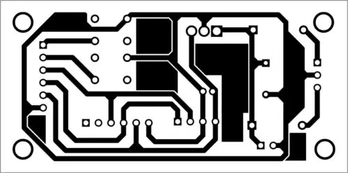
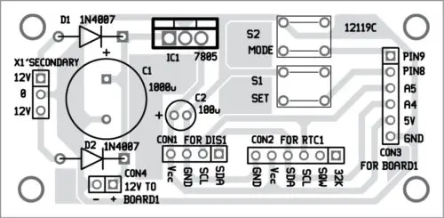
Figures 7 and 8 show the printed circuit board layout and component placement designed to integrate the Arduino, RTC, display and other elements. With the proper header inclusions and library imports, the software enables the hardware interfacing and full functionality of the real-time clock and temperature display project.