Summary of Arduino Laser Trip Wire
This article details an Arduino-based security system featuring keypad entry, LCD display, and a laser trip wire. The project allows users to arm or disarm the system via a password. When armed, a laser points at an LDR; if interrupted, the system triggers an alarm. It includes logic for LED indicators and brightness adjustment.
Parts used in the Arduino Laser Trip Wire:
- Arduino Uno
- 3 x 4 keypad
- 16 x 2 LCD screen
- Laser module/sensor
- Light dependent resistor (LDR)
- Buzzer
- 3 x 220 ohm resistors
- 1 x 10K resistor
- 1 x 10k potentiometer
- LED
- Wires
For this dandy little project you’ll need:
- Arduino – I’m using an Arduino Uno
- a 3 x 4 keypad
- a 16 x 2 LCD screen
- a laser module/sensor
- a light dependent resistor (LDR)
- a buzzer
- 3 x 220 ohm resistors
- 1 x 10K resistor
- 1 x 10k potentiometer (optional, it’s to adjust the LCD screen brightness)
- an LED
- and a ton of wires
So, first thing I did was to get the LCD and keypad working together.
For this I pretended that it was some sort of arm/disarm (or entry/exit) thing.
My code for this part is at: http://pastebin.com/YndLneqm.
Getting the LCD wired up was tricky as most wiring diagrams for it don’t show the last two pins wired up and these are required for the back light. Check my snazzy Fritzing wiring diagram to see how I wired up my LCD screen, pot (for adjusting brightness) and keypad. The pins for them all are also mentioned in my code.
NOTE: pin 1 isn’t used as whenever I wired something to pin 1 I experienced weirdness. Not sure why. I expect it’s something to do with the pins data uses?
If you don’t have the keypad.h library you’ll need to grab it from here: http://playground.arduino.cc/code/Keypad
I’ve added to it using a simple IF/ELSE statement to do one of two things.
I’ve added an LED and an integer called ‘armed’. Initially ‘armed’ equals zero, and ‘armedLed’ equals A0. I’m now having to tweak the rules and use the analog pins for digital components as I’m quickly running out of pins!
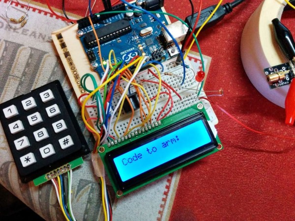
Basically here’s what’s happening: if the password is correct and armed=0 (in other words: the system is off) then it will clear the screen, display ARMED!, change armed to equal 1 and light the red LED. Finally it will display “Code to disarm:”. Otherwise, armed must equal 1 (system is on) so display DISARMED!, make armed=0 and display “Code to arm:”.
After getting success with armed/disarmed I went and dug out a laser sensor from my cheapo 37-in-1 sensor box and a photoresistor (a Light Dependent Resistor, LDR for short). The LDR goes to A1 with a 220 ohm resistor with one leg and taking its other leg to ground. The laser sensor goes to the positive LED leg and to ground. Now, when the system is armed the laser flicks on and is made to point at the LDR.
For more detail: Arduino Laser Trip Wire
- What components are required to build this project?
The project requires an Arduino Uno, a 3 x 4 keypad, a 16 x 2 LCD screen, a laser module, an LDR, a buzzer, various resistors, a potentiometer, an LED, and wires. - How do I adjust the LCD screen brightness?
You can use a 10k potentiometer connected to the circuit to adjust the LCD screen brightness. - Which pin should not be used on the Arduino for this wiring?
Pin 1 is not used because connecting something to it caused weirdness, likely due to data pins usage. - Where can I find the Keypad library if I do not have it?
The Keypad library can be grabbed from http://playground.arduino.cc/code/Keypad. - What happens when the correct password is entered while the system is off?
The screen clears, displays ARMED!, changes the armed status to one, lights the red LED, and shows the code to disarm. - How is the laser sensor connected in the circuit?
The laser sensor goes to the positive LED leg and to ground. - Where does the Light Dependent Resistor connect?
The LDR connects to analog pin A1 with a 220 ohm resistor to ground. - Can analog pins be used for digital components in this project?
Yes, the author uses analog pins for digital components like the LED because they are running out of standard digital pins.