Summary of Redesigning the RA-02 Breakout board module
The article describes redesigning an RA-02 (SX1278) LoRa breakout to be breadboard-friendly and safe for 5V hosts by adding level conversion, clearly labeled 3V/5V sides, and OE control. It covers pitfalls of the stock breakout (3V IO, multiple grounds, messy wiring), presents Mosfet and logic-IC converter approaches, shows tests with Arduino Uno (5V) and RP2040 Pico (3V), provides wiring, code, and explains enabling the converter via an OE pin.
Parts used in the RA-02 Breakout Module Project:
- RA-02 Breakout Module (Semtech SX1278 based)
- BSS138 N-MOSFET (for level shifting)
- 10k resistors (pull-ups/pull-downs for level conversion)
- 8-channel Logic level converter (example used in setup)
- Arduino Uno clone / Cytron Maker Uno (5V host used for testing)
- Raspberry Pi Pico / Maker Nano RP2040 (3V host used for testing)
- Solderable breakout PCBs / custom Arduino-type PCB with 8 level converters
- Wires and breadboard (for prototyping)
- Sandeep Mistry LoRa Library (Arduino library used in tests)
Story
The RA-02 Breakout module includes level converters
The RA-02 Breakout Module is designed to be beginner-friendly and compatible with breadboards.
 Many of them may possess one or more RA-02 Breakout modules. For those who do, they are undoubtedly aware of the challenges associated with using this specific breakout module.
The RA-02 module is an excellent piece of equipment, especially when integrated into a custom PCB that considers all its intricacies. However, using the RA-02 breakout module in its current form factor poses several unique challenges. If these challenges are unfamiliar to you, they can lead to frustrating moments or even permanent damage to the module.
What do these challenges entail?
1)The module utilizes Semtech’s SX1278 chip and operates at 3V. However, its IO pins are NOT compatible with 5V, despite appearing to function temporarily when supplied with 5V. This misconception has led many individuals, particularly on YouTube, to mistakenly believe that sending 5V logic signals to the module is safe.
So far, I haven’t come across any YouTube videos advising viewers to use a resistor divider or logic converter at the very least. Unfortunately, there seems to be a lack of awareness about this issue, and even those who are aware of it tend to remain silent about it.
The datasheet actually specifies the use of logic converters.
2)Incorporating logic converters involves introducing extra wiring, which can complicate a breadboard-based project.
3)You need to connect a total of 4 ground pins. Failing to connect all of them can lead to various issues, ranging from overheating to complete failure. This conclusion is based on my personal experience while researching this project.
4)Due to its lack of breadboarding compatibility, the current breakout module creates a messy setup with wires going everywhere, leading to unstable connections and other issues.
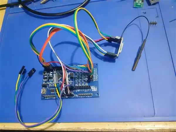
Essentially, something akin to the image depicted below:
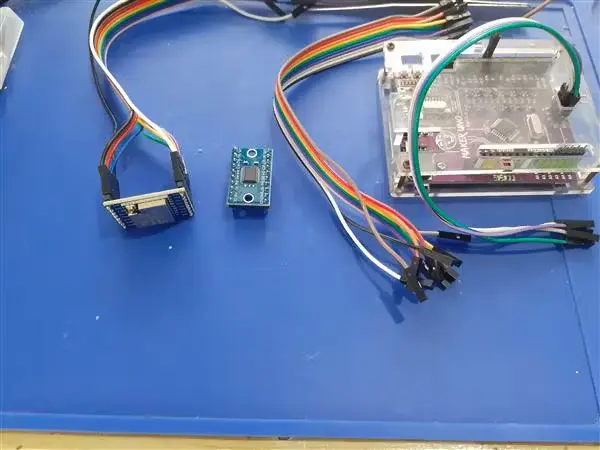
The image showcases my setup featuring an existing RA-02 Breakout Module, an 8-channel Logic converter, and an Arduino Uno clone, all interconnected with numerous wires to enable this configuration. It certainly involves a substantial amount of wiring.
Here is my proposed solution:
In my designs, I frequently utilize the BSS138 N-MOS Mosfet and 10k resistors for logic conversion on various LoRa PCBs. This solution is cost-effective and dependable, but it does require a significant amount of PCB space. For instance, to implement level conversion for all of the RA-02’s GPIO and IO pins, it would necessitate using 11 Mosfets and 22 10k resistors.
I frequently encounter the issue of dealing with numerous unnecessary wires, some of which even fail right after prototyping. To address this problem, I’ve created a few specialized PCB solutions, which have helped to some extent. However, relying solely on dedicated PCBs is not always the most ideal approach.
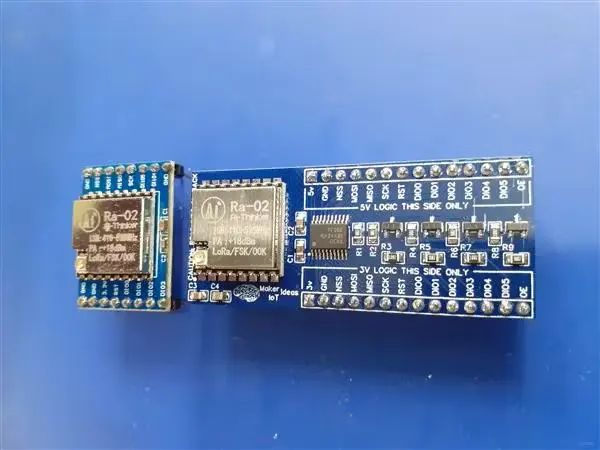
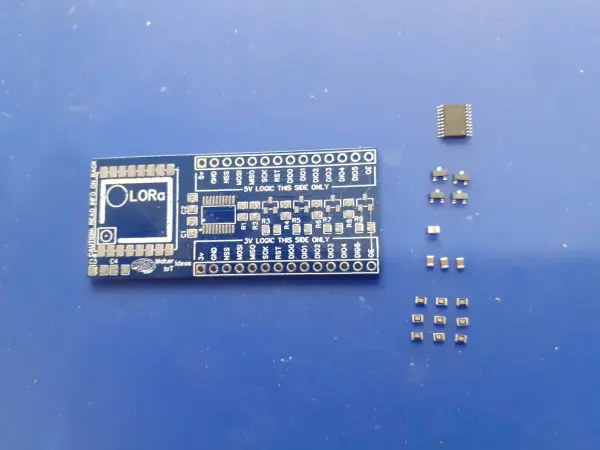
After considering the advantages of using a dedicated Logic Converter IC and Mosfet-based converters to achieve compatibility with breadboards, I found the idea promising. Consequently, I proceeded to design the following solution:
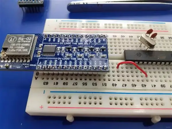
The breakout board module is designed to be breadboard compatible and features clearly marked pins to distinguish between the 3V and 5V sides of the module.
Module Testing:
Employing a 5V device
For my initial test, I opted to use an Arduino Uno Clone, as it is commonly available to most Makers and students. Specifically, I utilized Cytron’s Maker Uno platform, which comes with additional features like diagnostic LEDs, making prototyping significantly more convenient.
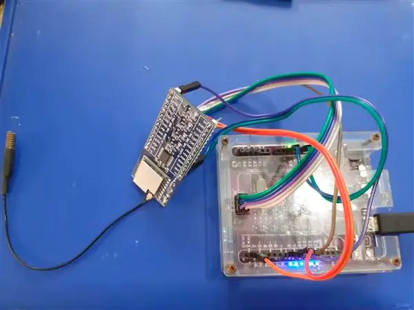
As evident from the setup, we only need to connect to the 5V logic side of the module, along with providing 3V and 5V power and ground connections to the module.
For this test, I utilized Sandeep Mistry’s LoRa Library, along with the Arduino IDE, to create a quick test sketch.
The connections are established as follows:
- RA-02 Module -> Maker Uno
- MISO -> D12
- MOSI -> D11
- SCK -> D13
- NSS -> D10
- RST -> D9
- DIO0 -> D2
- OE -> D8
Now, let’s delve into some crucial sections to gain a comprehensive understanding of how to effectively utilize the module:
Pin Declaration
#include <SPI.h> // include libraries

#include <LoRa.h> // I used Sandeep Mistry's LoRa Library, as it is easy to use and understand

const int csPin = 10; // LoRa radio chip select

const int resetPin = 9; // LoRa radio reset

const int irqPin = 2; // change for your board; must be a hardware interrupt pin
const int OEPin = 8; // Output Enable Pin, to enable the Logic Converter
Within the Setup function, some additional tasks need to be performed, especially because our Maker Uno (or your Arduino Uno) operates at 5V.
void setup() {
Serial.begin(115200); // initiate serial communication
pinMode(OEPin, OUTPUT); // Set up the OE pin as an output
digitalWrite(OEPin, HIGH); // Pull it High to enable the logic converter
while (!Serial);
Serial.println(“LoRa Duplex – Set spreading factor”);
// override the default CS, reset, and IRQ pins (optional)
LoRa.setPins(csPin, resetPin, irqPin); // set CS, reset, IRQ pin
if (!LoRa.begin(433E6)) { // initialize ratio at 433 MHz
Serial.println(“LoRa init failed. Check your connections.”);
while (true); // if failed, do nothing
}
LoRa.setSpreadingFactor(8); // ranges from 6-12, default 7 see API docs
Serial.println(“LoRa init succeeded.”);
}
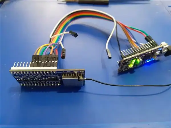
A comparison between the standard RA-02 Breakout module and one of my custom “Arduino-type PCBs”.
As observed, a significant number of wires are required to establish the connections in this setup. Additionally, it’s essential to mention that there are only 8 level converters on this ATMEGA328P PCB. To utilize all of the RA-02’s GPIO, an external logic converter must be added as well.
Using a 3v Device:
For my second test, I opted for a more adventurous approach by attempting to use the new Raspberry Pi Pico (RP2040 Microprocessor). I have several Pico boards lying around but haven’t explored them much because I’m not fond of using MicroPython or CircuitPython, and the Arduino Core for the RP2040 is relatively new. To simplify things, I chose to work with a development board that offers useful diagnostic features. Additionally, I’ll also conduct a test using an original Pi Pico board to make it accessible to a wider audience.
Once again, I employed Sandeep Mistry’s LoRa Library and utilized the exact same Arduino sketch used in the Maker Uno test. However, I had to modify the pin numbers because the RP2040 utilizes different pins for its SPI interface.
Maker Nano RP2040 RA-02 Breakout Module
NSS 17
MOSI 19
MISO 16
SCK 18
RST 9
DIO0 8
In this scenario, there is no need for the OE pin since the RP2040 is a native 3V device. Consequently, the level converter can remain disabled, with its pins in tri-state (high impedance) mode.
Upon examining the code, it closely resembles the Maker Uno’s code, with the only difference being the alteration required in the Pin declarations.
#include <LoRa.h>

const int csPin = 17; // LoRa radio chip select

const int resetPin = 9; // LoRa radio reset

const int irqPin = 8; // change for your board; must be a hardware interrupt pin

byte msgCount = 0; // count of outgoing messages

int interval = 2000; // interval between sends

long lastSendTime = 0; // time of last packet send

// Note that SPI has different names on the RP2040, and it has 2 SPI ports. We used port 0

// CIPO (Miso) is on pin 16

// COPI (Mosi) is on pin 19

// SCK is on pin 18

// CE/SS is on pin 17, as already declared above
To simplify matters, I avoided using a breadboard for this setup.
To simplify the process and avoid using a breadboard, I opted to conduct the Original Pi Pico test using the Maker Pi Pico PCB. This PCB functions as a comprehensive breakout module, equipped with detailed pin numbers and diagnostic LEDs. While it utilizes a native Pi Pico, directly soldered to the PCB through castellated holes, it is not a true standalone Pico. Nevertheless, using this setup for the test ensures that the pins are labeled exactly the same as on the original Pico, making my work more convenient.
The code used for the Maker Nano RP2040 works flawlessly, requiring no modifications.
Given the length of this post, I’ve chosen not to include my tests of the ESP-12E (NodeMCU) or ESP32 development boards. Rest assured, they also performed as expected.
Schematics
Code
#include <SPI.h> // include libraries
#include <LoRa.h>
const int csPin = 10; // LoRa radio chip select
const int resetPin = 9; // LoRa radio reset
const int irqPin = 2; // change for your board; must be a hardware interrupt pin
const int OEPin = 8; // Output Enable Pin
byte msgCount = 0; // count of outgoing messages
int interval = 2000; // interval between sends
long lastSendTime = 0; // time of last packet send
void setup() {
Serial.begin(115200); // initialize serial
pinMode(OEPin,OUTPUT);
digitalWrite(OEPin,HIGH);
while (!Serial);
Serial.println("LoRa Duplex - Set spreading factor");
// override the default CS, reset, and IRQ pins (optional)
LoRa.setPins(csPin, resetPin, irqPin); // set CS, reset, IRQ pin
if (!LoRa.begin(433E6)) { // initialize ratio at 915 MHz
Serial.println("LoRa init failed. Check your connections.");
while (true); // if failed, do nothing
}
LoRa.setSpreadingFactor(8); // ranges from 6-12,default 7 see API docs
Serial.println("LoRa init succeeded.");
}
void loop() {
if (millis() - lastSendTime > interval) {
String message = "Testing Arduino and RA-02 breakout "; // send a message
message += msgCount;
sendMessage(message);
Serial.println("Sending " + message);
lastSendTime = millis(); // timestamp the message
interval = random(2000) + 1000; // 2-3 seconds
msgCount++;
}
// parse for a packet, and call onReceive with the result:
onReceive(LoRa.parsePacket());
}
void sendMessage(String outgoing) {
LoRa.beginPacket(); // start packet
LoRa.print(outgoing); // add payload
LoRa.endPacket(); // finish packet and send it
msgCount++; // increment message ID
}
void onReceive(int packetSize) {
if (packetSize == 0) return; // if there's no packet, return
// read packet header bytes:
String incoming = "";
while (LoRa.available()) {
incoming += (char)LoRa.read();
}
Serial.println("Message: " + incoming);
Serial.println("RSSI: " + String(LoRa.packetRssi()));
Serial.println("Snr: " + String(LoRa.packetSnr()));
Serial.println();
- Can the RA-02 module be driven directly with 5V logic?
No, the RA-02 uses the SX1278 which operates at 3V and its IO pins are not compatible with 5V; the datasheet specifies using logic converters. - What is the recommended way to interface 5V devices with the RA-02?
Use logic level converters such as BSS138 MOSFET based converters or a dedicated logic converter IC and enable them using an OE pin as described. - Do I need to connect multiple ground pins for the RA-02?
Yes, the article states you need to connect a total of 4 ground pins; failing to do so can cause overheating or failure. - How can I make the RA-02 breadboard friendly?
Design a breakout that is breadboard compatible, clearly marks 3V and 5V sides, and includes integrated level conversion to reduce messy wiring. - How is the logic converter enabled when using a 5V Arduino?
Set the OE (Output Enable) pin as an output and pull it HIGH to enable the logic converter before initializing LoRa. - Is a logic converter required when using a 3V device like the RP2040?
No, with a native 3V device such as the RP2040 the level converter can remain disabled and in tri-state (high impedance) mode. - Which library was used for the LoRa tests in the article?
Sandeep Mistry's LoRa Library was used for both Arduino and RP2040 tests. - What SPI and control pins are used for the Maker Uno test setup?
MISO to D12, MOSI to D11, SCK to D13, NSS to D10, RST to D9, DIO0 to D2, and OE to D8 on the Maker Uno. - Does the article provide code for testing the RA-02 breakout?
Yes, the article includes Arduino sketches for initializing LoRa, enabling the OE pin, sending messages, and receiving packets.