Summary of Project work3:Arduino code and the circuit diagram using arduino
Summary: The article describes an Arduino-based "music garden" using eight IR distance sensors and eight sound outputs. Each sensor triggers a corresponding sound when detection changes from no-person to person, with timing limits to stop sounds after a set duration. The author provides the full Arduino code, explains variables (previous, time, limit), a flowchart for one pot, and mentions a circuit diagram where sound cards and sensors are grouped for wiring convenience.
Parts used in the music garden:
- Arduino (microcontroller)
- 8 IR distance sensors (IRD)
- 8 sound cards / music output modules
- Wiring/jumpers
- Power supply for Arduino and sound cards
- 8 digital I/O pins for sensors (pins 30–37)
- 8 digital I/O pins for music outputs (pins 38–45)
- Flower pots or mounts for sensors and sound modules
In order to realise the “music garden”,the most important part is the Arduino code and circuit diagram.
First of all,I will present my Arduino code:(I will show you the way I think as a flow chart at first)
Flow Chart:
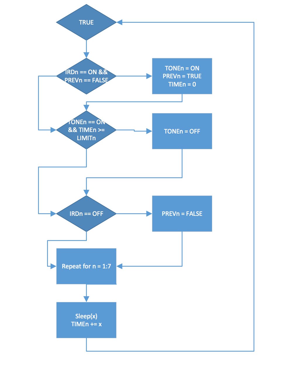 Details:this flow chart is a mode for one single flower pot
IRDs means the sensor
PREVn means the records about whether there are people in front the sensor
When turn on the IRDn and the PREVn equals FALSE,Which will trigger the sound card to play tone(TONEn),then set the PREVn equals TRUE,and time(TIMEn) set up to 0,and that cycle repeats.
Code:
const int sets = 8;
const int tick = 100;
int IRD[sets] = {30, 31, 32, 33, 34, 35, 36, 37};
int music[sets] = {38, 39, 40, 41, 42, 43, 44, 45};
bool previous[sets] = {false, false, false, false, false, false, false, false};
double limit[sets] = {2.0, 2.0, 2.0, 2.0, 2.0, 2.0, 2.0, 2.0};
double time[sets] = {0.0, 0.0, 0.0, 0.0, 0.0, 0.0, 0.0, 0.0};
void setup() {
// put your setup code here, to run once:
for (int i = 0; i < sets; ++i) {
pinMode(IRD[i], INPUT);
pinMode(music[i], OUTPUT);
digitalWrite(music[i], HIGH);
}
}
void loop() {
// put your main code here, to run repeatedly:
int val;
for (int i = 0; i < sets; ++i) {
val = digitalRead(IRD[i]);
if (val == LOW && !previous[i]) {
digitalWrite(music[i], LOW);
previous[i] = true;
time[i] = 0.0;
}
if (val == LOW && time[i] >= limit[i]) {
digitalWrite(music[i], HIGH);
}
if (val == HIGH) {
previous[i] = false;
digitalWrite(music[i], HIGH);}}
delay(tick);
for (int i = 0; i < sets; ++i) {
time[i] += (double)tick/1000;
}
}
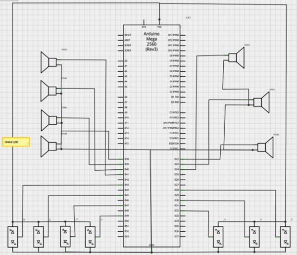
Secondly:I will present my circuit diagram
In practice,I did not obey strictly according to this diagram,I put all sound cards and sensors together which will be easy for me to connect the circuit.
For more detail: Project work3:Arduino code and the circuit diagram
- How many sensor and sound channels does the project use?
The code and description use eight sensor channels and eight corresponding sound outputs. - How does a sensor trigger a sound?
If a sensor reads LOW and previous is false, the code sets the music output LOW to play tone, sets previous true, and resets its time to 0. - How long will a sound play?
A sound plays until its time exceeds the corresponding limit value (default 2.0 seconds), at which point the code sets the music output HIGH to stop it. - What is the purpose of the previous array?
previous records whether a person was already detected to ensure the sound triggers only on change from no-person to person. - How often does the loop update timings?
The loop uses a delay tick of 100 ms and increments each channel time by tick/1000 seconds (0.1 s per loop). - How are the sensors and sound cards wired practically?
The author groups all sound cards and sensors together for easier wiring, rather than strictly following the diagram. - What pins are assigned to sensors and music outputs?
Sensors use pins 30–37 and music outputs use pins 38–45 as defined in the code. - What initial state is set for music outputs in setup?
Each music output pin is set as OUTPUT and digitalWrite HIGH in setup.