
Summary of Police Lights using an Arduino
This article details a DIY police light project using an ATMega 2650 microcontroller. The system drives eight high-brightness LEDs (four red and four blue) in various flashing patterns, such as alternating flashes and sequential cycles. The author provides hardware setup instructions for a breadboard and shares Arduino code to control the lights, noting that users can modify timings or swap components like transistors and shift registers for expanded capabilities.
Parts used in the Police Lights Project:
- 4x red LED's (high brightness)
- 4x blue LED's (high brightness)
- 8x 100 ohm resistors
- 1x ATMega 2650
- 22AWG wire
- 1x breadboard
**DISCLAIMER**
I do not and will not take responsibility for anyone who gets in trouble for this, by either imitating emergency personnel, or using without a permit/lisence.
Updates!
-I have shortened the code
-Changed 16 LED’s to 8
-Changed/added more flash patterns
-Renamed variables
As promised, this is the ATMega 2650 version of the police lights I originally did on my Duemilanove.
What you will need:
4x red LED’s (high brightness) You will want extra bright red LED’s because the ones I used are not very bright compared to the blue
4x blue LED’s (high brightness)
8x 100 ohm resistors
1x ATMega 2650 (The revision version does not matter)
22AWG wire
1x breadboard

Optional:
You can use transistors to use a lot of lights and not have to have as much code, or as many outputs being used. Just replace the LED’s with the transistors you want to use. I plan on using blue LED light strips with transistors to make this as easy as possible.
Or even use shift registers and have a HELL of a lot of LED’s hooked up.
Step 1: The Hardware
Considering you have installed the MEGA drivers and can program it, I will show you how to make awesome looking police lights.
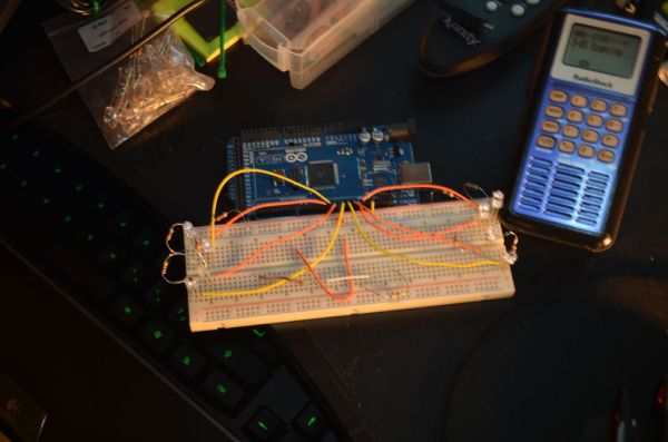
First, you want to grab your breadboard, and some wire. You want to have it hooked up similar to the way I have it hooked up I the first picture. This makes it look better, stay together better, and make it easier to hook it up.
You will notice that the way I hooked it up looks a little weird, don’t fret. I have it programmed to use these pins so you don’t have to figure them all out.
I know I don’t provide a schematic, but it would be a HUGE pain to draw one up, and it would not look very good or understandable with this many outputs. I figured you can see how to hook it up enough to actually hook it up. Follow my Duemilanove version if you can’t figure this out. This is just double the outputs of what that is.
Step 2: The Code
Now that you have it all hooked up, you will want to paste the code into your Arduino IDE. You can change this code any way you want to make it look more like police lights, or even like an oversized Nightrider if you use all red LED’s. So feel free to modify it, you don’t have to say that I wrote the code, just mention me for giving you the idea or the base to branch your project off of.
Patterns:
-Flash one side 3 times
-Flash the other side 3 times
-Flash one side one time, then the other side one time, (alternating happening 7 times)
-Flash one side twice, then the other side twice (happens 6 times)
Feel free to mess with the timings, or how many cycles it does of each to your liking.
The code:
/*
This sketch will flash 8 LED’s in certain patterns. The “for” statement really helped cut down on the code (It cut the size in half).
This project is meant for the blue lights I will be using in my vehicle as a volunteer firefighter, so the variables are named as such.
*/
//Declaring the front lights
const int GrillTopLeft = 5;
const int GrillTopRight = 6;
const int GrillBottomLeft = 7;
const int GrillBottomRight = 8;
//For the lights in by the rear-view mirror, just use the outputs for the REAR LED’s so it looks awesome, and you don’t have to use 4 more outputs.
//Declaring the rear lights
const int TaillightLeft = 9;
const int ReverselightLeft = 10;
const int ReverselightRight = 11;
const int TaillightRight = 12;
void setup() {
//Declares the front LED’s as output
pinMode(GrillTopLeft, OUTPUT);
pinMode(GrillTopRight, OUTPUT);
pinMode(GrillBottomLeft, OUTPUT);
pinMode(GrillBottomRight, OUTPUT);
//Declares the rear LED’s as outputs
pinMode(TaillightLeft, OUTPUT);
pinMode(ReverselightLeft, OUTPUT);
pinMode(ReverselightRight, OUTPUT);
pinMode(TaillightRight, OUTPUT);
}
4x blue LED’s (high brightness)
8x 100 ohm resistors
1x ATMega 2650
For more detail: Police Lights using an Arduino
- What microcontroller is used in this project?
The project uses an ATMega 2650. - How many LEDs are required for the basic build?
You need 4 red LEDs and 4 blue LEDs. - Can I use transistors instead of direct LED connections?
Yes, you can replace LEDs with transistors to drive more lights without using as many outputs. - Does the code allow for pattern modification?
Yes, you can change timings and the number of cycles to customize the look. - What resistor value is needed for the LEDs?
The project requires 8x 100 ohm resistors. - Is a schematic provided for the wiring?
No, the author states drawing a schematic would be painful and suggests following their visual description or a previous Duemilanove version. - Can shift registers be added to the project?
Yes, shift registers can be used to hook up a large number of LEDs. - What programming environment is used for the code?
The code is intended to be pasted into the Arduino IDE.
