Summary of Mastering Arduino Servo Control: A Comprehensive Tutorial
This article demonstrates building an Arduino servo control system using an IR remote and TSOP receiver. It details three circuit iterations: basic servo control, adding LEDs for signal indication, and integrating a 16x2 LCD for value display. The guide provides specific wiring instructions and code snippets for each configuration, allowing users to customize servo positions based on remote button inputs while visualizing the process through lights or an LCD screen.
Parts used in the Arduino Servo Control Remote System:
- Arduino UNO
- TSOP IR receiver
- Servo motor
- IR remote
- Three LEDs of various colors
- 16×2 LCD
- 10K potentiometer
- Jumper wires and a breadboard
- 220-ohm resistors
- USB cable utilized for code uploading
Introduction
Hello enthusiasts, welcome back to our latest post featuring Arduino UNO. In this article, we’ll demonstrate how to create your own Arduino servo control remote system. This setup involves utilizing an IR remote control for wireless signal transmission, coupled with a TSOP IR receiver module on the receiving end. To control the servo motor, a simple button press on the IR remote suffices. Explore additional articles on IoT and basic electronics. Ensure accurate connections and upload the code as instructed.
Description
Initially, the servo motor is positioned at 0 degrees.
When you press buttons on the IR remote, the Arduino servo control initiates positional changes.
The code already specifies various positions and their corresponding codes, allowing customization as needed.
For instance, pressing button 1 on the IR remote triggers rotation of the servo motor to a specific position.
This circuit is the simplest setup for this project. Now, LEDs are integrated with the Arduino, enabling them to automatically illuminate upon pressing the IR remote buttons.
The inclusion of LEDs in the circuit serves the purpose of indicating signal reception by the Arduino.
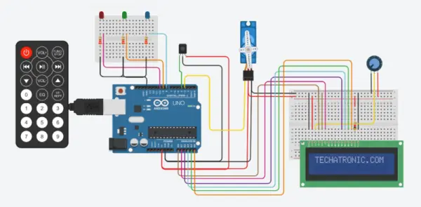
In the third circuit iteration, an LCD module is incorporated, providing visibility into the values received by the Arduino.
Feel free to explore our Arduino IR remote control project for reference.
Components Required for Arduino with Servo Control system
Here is a rundown of the necessary components. Verify that each component is functioning correctly and possesses the accurate values:
– Arduino UNO
– TSOP IR receiver
– Servo motor
– IR remote
– Three LEDs of various colors
– 16×2 LCD
– 10K potentiometer
– Jumper wires and a breadboard
– 220-ohm resistors
– USB cable utilized for code uploading
Circuit for arduino servo control
This post includes three circuit diagrams, providing options for you to select based on your preference. Ensure precision and firmness in all connections. Utilize a breadboard to establish the common connections as illustrated in the diagrams.
Only with Servo motor
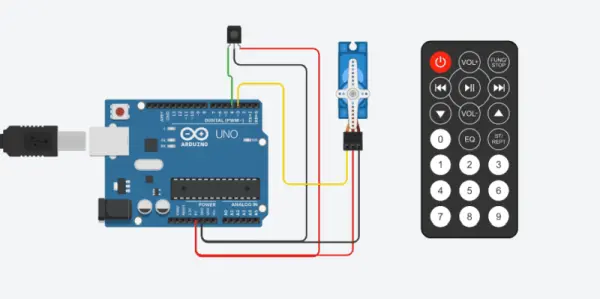
Connect the negative power lead to the Arduino’s GND pin.
Then, attach the OUT lead of the IR receiver to the digital-4 pin of the Arduino.
Regarding the servo motor, connect the VCC wire to the 5-volt pin of the Arduino.
Link the GND wire to the GND pin of the Arduino.
Lastly, connect the signal wire of the servo motor to the digital-3 pin of the Arduino for this remote-controlled servo. Your connections are now successfully established.
Servo motor Arduino code
#include
#include
Servo s1;
int RECV_PIN = 4;
int S ;
IRrecv irrecv(RECV_PIN);
decode_results results;
void setup()
{
Serial.begin(9600);
s1.attach(3);
Serial.println(“Enabling IRin”);
irrecv.enableIRIn();
Serial.println(“Project Started”);
s1.write(0);
}
void loop()
{
if (irrecv.decode(&results))
{
S = results.value, HEX ;
Serial.println(S);
irrecv.resume(); // Receive the next value
}
if(S == 2295 )
{
s1.write(90);
}
if(S == -30601 )
{
s1.write(180);
}
if(S == 18615 )
{
s1.write(120);
}
if(S == 10455 )
{
s1.write(70);
}
if(S == -22441 )
{
s1.write(0);
}
delay(10);
}
arduino With LEDs and Servo Motor
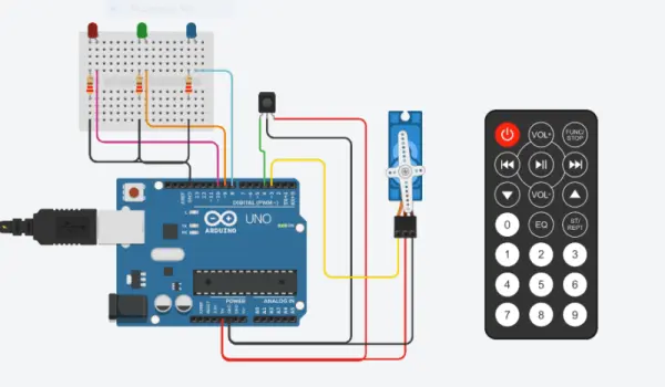
Link the GND wire of the servo motor to the GND pin on the Arduino.
Connect the positive power leg of the TSOP IR receiver to the 5 volts pin on the Arduino.
Then, attach the negative power leg to the GND pin on the Arduino.
Next, connect the OUT leg of the IR receiver to the digital-4 pin on the Arduino.
Connect the signal wire of the servo motor to the digital-3 pin on the Arduino.
Take an LED and connect its positive leg to the digital-8 pin on the Arduino. Attach the positive leg of the second LED to the digital-9 pin on the Arduino.
Connect the positive leg of the third LED to the digital-10 pin on the Arduino.
Connect the negative legs of all three LEDs to the GND pin on the Arduino using a 220 ohm resistor.
Your connections are now complete.
servo motor arduino code with IR remote
#include
#include
Servo s1;
int RECV_PIN = 4;
int S ;
IRrecv irrecv(RECV_PIN);
decode_results results;
void setup()
{
Serial.begin(9600);
s1.attach(3);
Serial.println(“Enabling IRin”);
irrecv.enableIRIn();
Serial.println(“Project Started”);
pinMode(8,OUTPUT);
pinMode(9,OUTPUT);
pinMode(10,OUTPUT);
s1.write(0);
}
void loop()
{
if (irrecv.decode(&results))
{
S = results.value, HEX ;
Serial.println(S);
irrecv.resume(); // Receive the next value
}
if(S == 2295 )
{
s1.write(90);
digitalWrite(8,HIGH);
digitalWrite(9,LOW);
digitalWrite(10,LOW);
}
if(S == -30601 )
{
s1.write(180);
digitalWrite(8,LOW);
digitalWrite(9,HIGH);
digitalWrite(10,LOW);
}
if(S == 18615 )
{
s1.write(60);
digitalWrite(8,LOW);
digitalWrite(9,LOW);
digitalWrite(10,HIGH);
}
if(S == 10455 )
{
s1.write(0);
digitalWrite(8,LOW);
digitalWrite(9,LOW);
digitalWrite(10,LOW);
}
delay(10);
}
Arduino With 16×2 LCD and Servo Motor

Utilize an LED, connecting its positive leg to the digital-8 pin on the Arduino.
Proceed by attaching the positive leg of the second LED to the digital-9 pin on the Arduino.
Connect the positive leg of the third LED to the digital-10 pin on the Arduino.
Following this, connect the negative legs of all three LEDs to the GND pin of the Arduino via a 220 ohm resistor, as illustrated above.
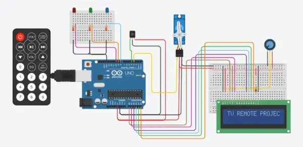
Arduino With 16×2 LCD and Servo Motor
#include
#include
#include “LiquidCrystal.h”
LiquidCrystal lcd(A0, A1, A2, A3, A4, A5);
Servo s1;
int RECV_PIN = 4;
int S ;
IRrecv irrecv(RECV_PIN);
decode_results results;
void setup()
{
Serial.begin(9600);
s1.attach(3);
lcd.begin(16,2);
Serial.println(“Enabling IRin”);
irrecv.enableIRIn();
Serial.println(“Project Started”);
pinMode(8,OUTPUT);
pinMode(9,OUTPUT);
pinMode(10,OUTPUT);
s1.write(0);
lcd.setCursor(0,0);
lcd.print(“TECHATRONIC.COM “);
delay(2000);
lcd.setCursor(0,0);
lcd.print(“TV REMOTE PROJECT “);
}
void loop()
{
if (irrecv.decode(&results))
{
S = results.value, HEX ;
Serial.println(S);
irrecv.resume(); // Receive the next value
}
if(S == 2295 )
{
s1.write(90);
digitalWrite(8,HIGH);
digitalWrite(9,LOW);
digitalWrite(10,LOW);
lcd.setCursor(0,1);
lcd.print(“90 Dgree B led “);
}
if(S == -30601 )
{
s1.write(180);
digitalWrite(8,LOW);
digitalWrite(9,HIGH);
digitalWrite(10,LOW);
lcd.setCursor(0,1);
lcd.print(“180 Dgree G led “);
}
if(S == 18615 )
{
s1.write(60);
digitalWrite(8,LOW);
digitalWrite(9,LOW);
digitalWrite(10,HIGH);
lcd.setCursor(0,1);
lcd.print(“60 Dgree R led “);
}
if(S == 10455 )
{
s1.write(0);
digitalWrite(8,LOW);
digitalWrite(9,LOW);
digitalWrite(10,LOW);
lcd.setCursor(0,1);
lcd.print(“0 Dgree led OFF “);
}
delay(10);
}
About the Code
Initially, we define the data type for each variable and subsequently assign their respective values. Following this, we specify the pin modes for every input or output pin utilized in the setup. Within the loop function, we acquire user input to facilitate ongoing processes. To execute specific operations, we utilize if conditional statements, ensuring execution only if the foundational condition proves true.
- How does the servo motor react when buttons are pressed?
The servo motor initiates positional changes corresponding to the specific button codes received from the IR remote. - What is the initial position of the servo motor?
The servo motor is initially positioned at 0 degrees before any buttons are pressed. - Does the circuit include LEDs to indicate signal reception?
Yes, LEDs are integrated to automatically illuminate upon pressing IR remote buttons to indicate signal reception by the Arduino. - What function does the 16×2 LCD module serve?
The LCD module provides visibility into the values received by the Arduino and displays the current servo angle status. - Can I customize the positions associated with remote buttons?
Yes, the code specifies various positions and their corresponding codes, allowing customization as needed. - Which pin connects the OUT lead of the IR receiver?
The OUT lead of the IR receiver is connected to digital-4 pin of the Arduino. - What happens if the received code equals 2295?
If the received code equals 2295, the servo motor rotates to 90 degrees and the first LED turns on. - How are the negative legs of the LEDs connected?
The negative legs of all three LEDs are connected to the GND pin of the Arduino using a 220 ohm resistor.