Summary of Make Wired Robotic Arm Edge to “Wireless” with DIY Arduino and XBee
This article details the modification of a wired Robotic Arm Edge into a wireless system using a custom "RevIO" Arduino clone and a DIY three-motor driver PCB. The project integrates XBee Series 1 modules for wireless communication, with an optional Bluetooth alternative. It covers the construction of the motor driver board from scratch, its design as a "piggy back" module for the RevIO, and the creation of a PC-based GUI using Processing to control the arm's motors.
Parts used in the Wireless Robotic Arm:
- H-Bridge Motor Driver IC (SN754410 or L293D)
- 1K Resistor
- 3mm Red LED
- Slide DPDT Switch
- 2x6 Male Header Connector
- 14-pin Male Header Connectors
- 2-pin Male Header Connector (Right Angle)
- 6-pin Female Connector (Right Angle)
- 16-pin IC Socket
- Multipurpose PC Board with 417 holes
- Wire
- RevIO Board or Arduino Clone
- XBee Series 1 Modules
- XBee Adapter Boards
- Bluetooth Modem (Blue SMiRF Gold or Silver) - Optional
UPDATE: Added Schematic, Top Layer PCB, Bottom Layer PCB, and both Top, Bottom PCB images
When I finished the “RevIO” – an Arduino Clone that has the different way of exposing pins usage. I decided to go further to the next project. To test my “RevIO” board that it could do the bigger task than just blinking the LED!
I modified the Wired Robotic Arm Edge to Wireless controlled, using my “RevIO” and DIY Three-Motor Driver ICs PCB together with XBee Series 1 module.

This instructables introduces the way I constructed Three-Motor Driver ICs PCB from scratch. Then using it as the “piggy back” on my “RevIO” Board.
To control the Robotic Arm, I designed the GUI (Graphical User Interface) with the Processing on the PC and Arduino sketch for driving the motors.
I also added the 6-pin socket as an alternative to use Bluetooth module (Sparkfun’s Bluetooth Modem – Blue SMiRF Silver, or Bluetooth Modem – Blue SMIRF Gold.)
Again I am going to use the same presentation method as Build “The RevIO” (Arduino Clone) My Way, to build the board using the graphical illustrations, together with the photos of actual build of the board.
Step 1: Build the Robotic Arm Edge
I got the Robotic Arm Edge Kit from TPE Shop in Thailand three months ago, while I was visiting my family in Thailand. But I did not do until I got back to USA a month later.
This is my very first Robotic Arm I ever encountered with. A week after I got back, I started to constructed the kit. I spend about four hours to build and pause to take pictures for this instructables.
I will not show you how I managed to put the kit together, but here is the collage of how I put the Robotic Arm together from the start to finish!
Step 2: Parts
IC1, IC2, IC3 H-Bridge Motor Driver 1A, SN754410 (Sparkfun #COM-00315) or L293D (Digikey#497-2936-5-ND)
R1 – 1K Resistor (Radio Shack #271-1321 or Digkey #PPC1.0KW-1CT-ND)
LED1 – 3mm Red LED (Digikey #160-1708-ND)
S1 – Slide DPDT Switch (Digikey #401-2000-ND)
JP1 – 2×6 Male Header Connector, Straight
JP2, JP3 -(2) 14-pin Male header, extra long pin or use shield stacking headers (Adafruit ID#85)
JP4 – 2-pin Male Header Connector, Right Angle
JP5 – 6-pin Female Connector, Right angle
16-pin IC Socket (Radio Shack #276-1998)
Multipurpose PC Board with 417 holes (Radio Shack #276-150)
Wire
The RevIO or any kind of Arduino
Note: In case of using Arduino or others Arduino Clone you needed to make the Motor Control Board to match those Arduino.
Other parts:
2 XBee Modules I got the Series 1 from AdaFruit
2 Xbee Adapter Board from AdaFruit
Alternativel part:
Bluetooth Modem – Blue SMiRF Gold (Sparkfun# WRL-10268)
or Bluetooth Modem – Blue SMiRF Silver (Sparkfun# WRL-10269)
Step 3: Layout & Schematic
As mentioned in the intro. I planned to use this motors driver board as a “piggy back” on the RevIO PCB. So I obtained the same PCB (Radio Shack #276-150) to match my RevIO’s exposed pins. I tried to use the plain PCB (Radio Shack #276-149) so I could put the three H-Bridge Motors Drivers in parallel to the width of the PCB, but that did not worked! Because the holes on the width side was one hole short of the RevIO.
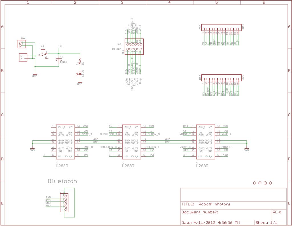
Notice that I placed the board by having the two row of individual holes on top and three rows of individual holes on the bottom. So it matches the layout of the RevIO board.
Luckily, I could fit three H-Bridge Motor Drivers IC on the Multipurpose PC Board with 417 holes (Radio Shack #276-150) by put them one after another over the positive and negative rails in the middle of the board.
The other good thing was that there were enough space to put 2×6 male header, for motors control pins and led on the board. So I place them on the top left corner of the board next to the top 14-pin rail. And also there were enough space to put a 6-pin connector as an alternative for Bluetooth breakout board. (Bluetooth Modem – Blue SMiRF Gold (Sparkfun# WRL-10268) or Bluetooth Modem – Blue SMiRF Silver (Sparkfun# WRL-10269)) . So I placed it on the bottom right corner of the PCB.
R1 – 1K Resistor
LED1 – 3mm Red LED
For more detail: Make Wired Robotic Arm Edge to “Wireless” with DIY Arduino and XBee
- How was the robotic arm modified for wireless control?
The author converted the wired Robotic Arm Edge by adding a DIY three-motor driver PCB, XBee Series 1 modules, and a RevIO board. - What specific H-Bridge drivers were used in the project?
The project utilized SN754410 1A H-Bridge Motor Drivers or L293D chips. - Can Bluetooth be used instead of XBee for this project?
Yes, a 6-pin socket was added to allow the use of Blue SMiRF Gold or Blue SMiRF Silver Bluetooth modems as an alternative. - How was the motor driver board physically designed?
The board was built as a piggy back on the RevIO PCB using a Multipurpose PC Board with 417 holes to match the exposed pin layout. - What software was used to create the user interface?
A Graphical User Interface was designed using Processing on the PC to control the robotic arm. - Which Arduino variant is recommended for this build?
The project uses the author's custom RevIO board, though any Arduino or Arduino clone can be used if the motor control board is matched accordingly. - Why was the plain PCB not suitable for this project?
The plain PCB failed because the hole spacing on the width side was one hole short to align with the RevIO board. - Where was the 6-pin connector placed on the PCB?
The 6-pin connector for the Bluetooth breakout board was placed on the bottom right corner of the PCB.