Summary of Joystick Controlled Car
This article details the construction of a joystick-controlled car using an Arduino Uno R3, L293D motor driver, and two DC motors for movement alongside a servo motor for steering. The project involves assembling components on a breadboard, wiring power and signal lines, and writing custom C++ code to interpret joystick inputs for forward, backward, left, and right motion.
Parts used in the Joystick Controlled Car:
- Arduino Uno R3
- L293D Motor Control
- 2x DC Motor
- Servo Motor
- 2x 9v Battery (or 1 battery and 1 portable USB power supply)
- 2 Battery Caps
- Mini Breadboard
- B103 Analog Joystick
- Jumper Cables and Wires
- Small Screwdriver
- 4x miniature tires
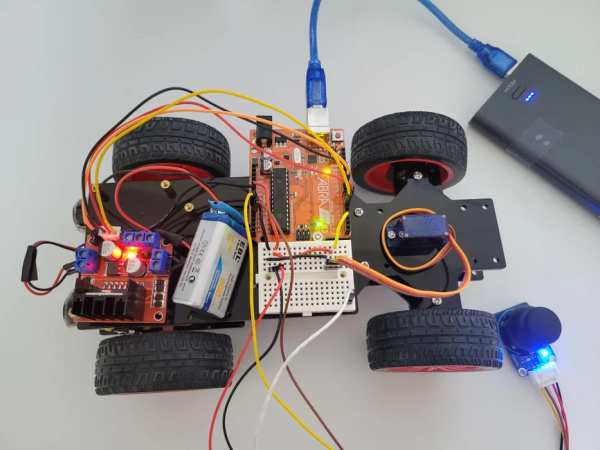
I have created a joystick-controlled car, capable of moving left, right, forwards, and backwards. I created this as I thought it would be a challenging project with a fun and exciting purpose.
Supplies
- Arduino Uno R3
- L293D Motor Control
- 2x DC Motor
- Servo Motor
- 2x 9v Battery (or 1 battery and 1 portable USB power supply)
- 2 Battery Caps
- Mini Breadboard
- B103 Analog Joystick
- Many Jumper Cables and Wires
- Small Screwdriver
- 4x miniature tires
Step 1: Research

The first step when beginning any project is the research! When I began this project, I first researched code online to get input from the joystick, code to make the servo rotate, and code to make the dc motors spin. My final product is the result of all the knoledge I gained from my research. Luckily you guys can skip this step, or is this entire tutorial technically your research? Well whatever it is, you’re ready to continue.
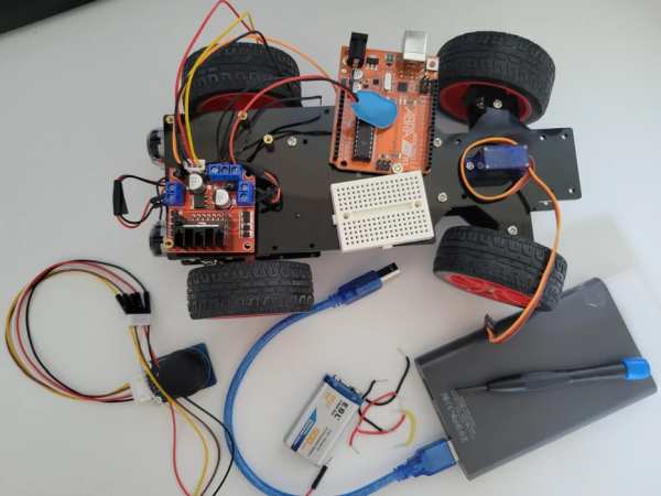
Step 2: Setup!
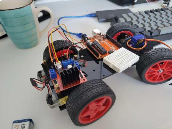
Attach your components to any frame of your choice. If you do not have a frame you can still create this project! Just not drive it like a real car. Make sure the 2 tires controlled by the DC Motors are at the back, and the 2 controlled by the Servo Motor are at the back.
Step 3: Wiring the Breadboard
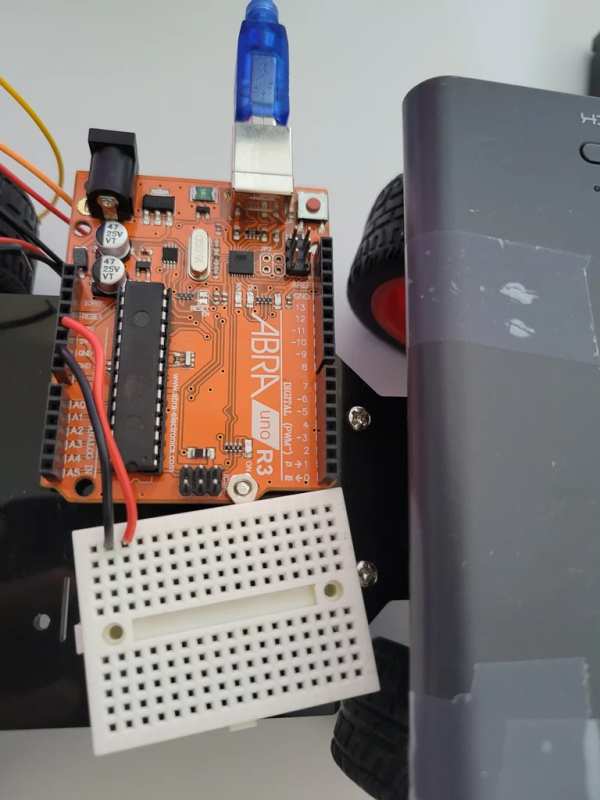
On the 2 furthermost left or right rails of your breadboard, attach them to the GND and 5V pins of your Arduino. Since mini breadboards don’t have individual power and ground rails, we will be using these 2 rails instead to supply the rest of the board with power and ground individually using wires. Don’t forget to give your ARDUINO power using a 9V battery or portable power supply.
Step 4: Wiring the L293D Motor Control and DC Motors
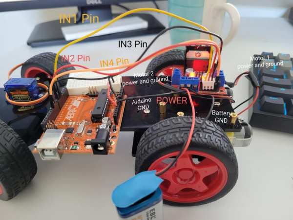
Firstly, using a screwdriver, loosen all of the blue ports. From both of the motor ports, connect power and ground to your DC Motors. From 1 of the set of 3 ports, connect it to the power cable of a 9V battery. And connect a second port to both, a ground pin on your Arduino, and the ground cable of your battery cap (Yes, both cables are in the same port. This is done so that the L293D and the Arduino can communicate). Connect the IN1 and IN2 ports to pins 5 and 6 of the Arduino. Connect IN3 and IN4 to pins 9 and 10.
Step 5: Wiring the Joystick
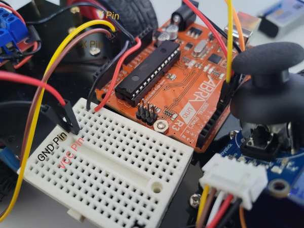
Using jumper cables, connect the Y or VRY pin of your joystick to pin A0. Connect X or VRX to pin A1. The Bt pin is not going to be used in this project. You can keep it disconnected for now, and later connect it to an unused rail in the breadboard. Connect the VCC and GND pins to the breadboard and supply them with power and ground using wires from the power and ground rails we set up in step 2.
Step 6: Wiring the Servo Motor
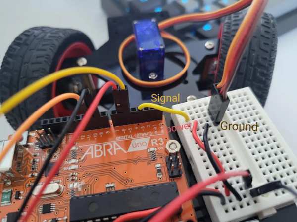
The Servo Motor has 3 pins; power, ground, and a signal pin. Plus all 3 pins into the breadboard. Give power and ground the respective connection, and connect the signal pin to pin 3 of the ARDUINO using a wire.
Step 7: Begin Your Code!
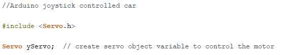
Create a new .ino file and name it whatever you like. The first thing we must add is our headers. This Program only uses 1 header which is for the servo motor. The header is: ” #include <Servo.h> “. Make sure you add this at the top of your code, outside any loops. Also, create the variable for your servo motor. Do this on the next line in the format of ” Servo servoName; “.
Step 8: Defining the Pins
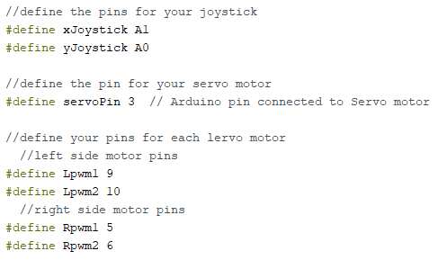
Define the pins for the X and Y pins of the joystick, the signal pin of your servo motor, as well as the pins of each DC Motor. Defining a variable rather than declaring it as a variable tells the compiler that the value of these variables will never change. It’s basically the same as a const int. It’s common practice to define variables that you know you won’t be changing. You can see how to define your variables in the image above.
Step 9: Declaring Data Type Variables
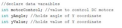
Declare a variable to store a value to control your DC motors, and a variable to hold the value and angle for the Y coordinate of your joystick. Declare these 3 variables as integers (int).
Step 10: Void Setup
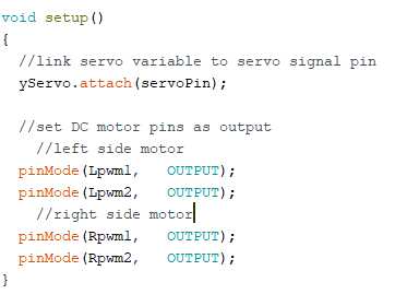
Let’s set up our pins! Well before we do that we need to set up the servo. We need to link our servo variable to the signal pin of the servo motor. We do this using the “attach” function which is programmed as: “servoName.attach (servoPin)”. Now we have to set up our PWM pins for our DC motors. All 4 of these pins need to be set as output as we will be using these pins to give a power-based signal to the motors to make them move at our desired speed. Make sure all of this is done in the function ” void setup() “.
Step 11: Reading Your Joystick and Moving the Servo
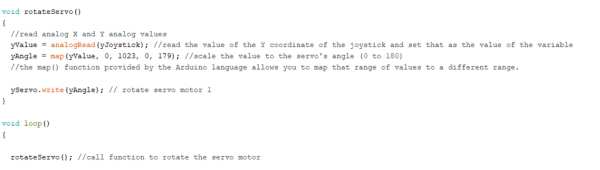
Before we start this step, let’s create a function called “void rotate Servo()”. This is the function we will put all our servo code in. Make sure you define this variable above void loop(). Then call this function in void loop by typing rotateServo();. We first need to set the value of the yValue variable. We want yValue to be the value of the y coordinate being provided from the joystick. We will do this using the analogRead() function. Next, we have to map the value of our yAngle variable. The map() function provided allows you to map a range of values to a new, different range. We will be mapping the variable from 0 to 179 since those are the angles our servo motor can move from. Lastly, we are going to rotate our servo by using the “write” function. The format is: ” servoVariableName.write(angleVariable); “. View the image above to see how it’s all done.
Step 12: Reading the X Coordinate to Move Rotate the Dc Motors
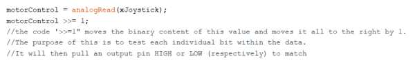
Similar to what we did before, we will be using analogRead() to get the X coordinate of the joystick and use this value to control the speed/RPM of our DC motors. After this we get the value for the motor variable, we need to read and text the binary value of this variable in order to output the right amount of POWER for our desired RPM. we will do this using “motorControl >>= 1”. the code “>>=1” moves the binary content of this value and moves it all to the right by 1. The purpose of this is to test each individual bit within the data. It will then pull an output pin HIGH or LOW (respectively) to match.
Step 13: Moving the Motor With the Joystick
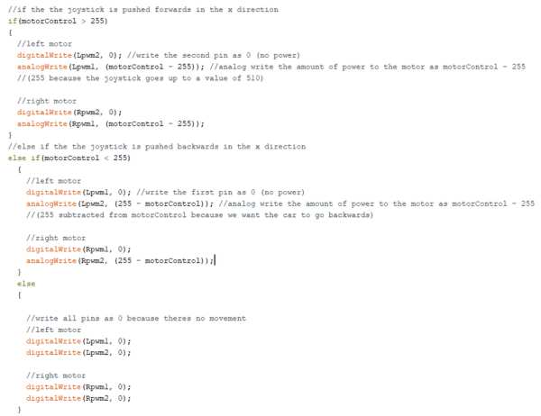
You’ve reached the end! Our last step is to make them motors move! We’ll be using an If, Else If, and Else statement to make it happen. To make the tires spin forwards, create an if statement with the condition of motorControl > 255. This is to check if the joystick is being pushed forwards. We will digitalWrite the second pin of the left and right motor as 0. This is because the second pin needs to receive no power while the first does, for the motor to spin forwards. The first pin will be given power using analogWrite. The value we will write will be the motorControl variable minus 255. We are subtracting 255 because the joystick goes up to a value of 510. To make the motors spin backwards, in an if-else statement with the condition motorControl < 255 to make sure the joystick is being pushed backwards, we will digitalWrite the first pin for each motor as 0 so that the motors spin backwards. The second pins will be given power using analogWrite. The value we will write will be 255 minus motor control. 255 will be subtracted from motorControl because we want the car to go backwards. Lastly, in an else statement, we will digitalWrite all pins to 0 so that the motors don’t spin when the joystick is at default.
Source: Joystick Controlled Car
- How do I connect the joystick to the Arduino?
Connect the Y or VRY pin to pin A0, the X or VRX pin to pin A1, and supply power and ground to the breadboard rails. - Can I use a single battery instead of two?
Yes, you can use one 9V battery and one portable USB power supply as an alternative to two 9V batteries. - Which pins should the DC motors be connected to?
Connect IN1 and IN2 to pins 5 and 6 of the Arduino, and IN3 and IN4 to pins 9 and 10. - What is the purpose of the map function in the code?
The map function converts the analog value from the joystick into a range between 0 and 179 degrees for the servo motor. - How does the code determine if the car moves forwards or backwards?
The code checks if the motorControl value is greater than 255 for forward motion or less than 255 for backward motion. - Does the Bt pin on the joystick need to be connected?
No, the Bt pin is not used in this project and can remain disconnected. - Which header file must be included at the top of the code?
You must include the Servo.h header file to control the servo motor. - What happens when the joystick is at its default position?
All motor pins are set to digital low so that the motors do not spin.