The objective of the DSP Shield project is to enhance the accessibility of Digital Signal Processing (DSP) concepts and applications, particularly by introducing DSP as a teaching tool for signal education at the undergraduate level or even earlier. The project aims to bridge the gap between DSP being predominantly practiced at the graduate level and creating opportunities for students to engage with DSP concepts earlier in their academic journey.
The DSP Shield project is a part of the broader initiative called ‘Lab In A Box’ which aims to transform the traditional electronics lab from being confined to university basements to a portable solution that students can carry with them.
In this context, the DSP Shield serves as a versatile platform for developing various DSP-based instruments. Its educational applications encompass functions like filters and spectrum analyzers, which can be utilized for teaching purposes. Additionally, it opens up possibilities for hobbyist applications such as guitar pedals and vocoders. As part of the Lab In A Box project, the DSP Shield can also be leveraged to create instrumentation tools like function generators, oscilloscopes, and network analyzers. These tools enable students to characterize and troubleshoot their constructed circuits, eliminating the need for access to expensive laboratory equipment.
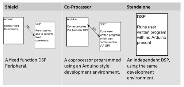
The board is designed to operate in one of three main modes:
1. Simple “Shield” Mode: In this mode, a pre-programmed binary is stored on the DSP Shield, which is physically stacked on top of the Arduino. The Arduino executes a library that allows it to control the binary on the DSP, enabling predetermined signal processing applications. For instance, it can apply filters to audio captured from the onboard audio codec using a given set of coefficients.
2. Co-processor Mode.
In another mode, the user has the flexibility to create their own DSP program by utilizing the Energia API, which is also stacked on top of the Arduino. The Energia API provides Arduino-style function calls and code, along with a user-friendly signal processing library. Communication between the Arduino and the DSP is facilitated by a pre-existing high-level messaging protocol. The code is uploaded to the DSP through the Arduino’s USB port, utilizing the shared serial bus.
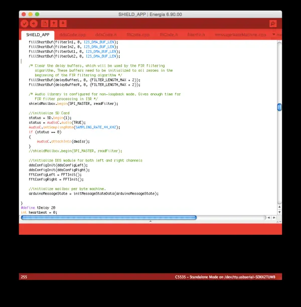
3. Standalone Mode
In the standalone DSP development board mode, the user can continue to write code as mentioned earlier, but the Arduino is no longer required. The DSP serves as the sole processor and can be programmed through its dedicated micro-USB port. Energia can still be utilized just as before, but Code Composer Studio is an alternative option for programming the DSP.
DSP Shield as an Arduino Shield (Shield Mode)
As previously mentioned, the DSP Shield offers the functionality of a traditional Arduino Shield when used in “Shield Mode”. In this mode, the DSP Shield can be employed for various purposes such as signal generation, FIR filtering, IIR filtering, FFT/Spectral Analysis, and more. These functionalities can be achieved by sending commands to the DSP Shield from an Arduino sketch. It’s important to note that this mode differs from directly programming the DSP Shield using Energia, as described in the subsequent section.
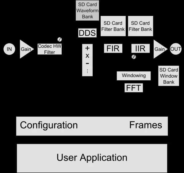
During Shield Mode, the DSP Shield operates with a pre-compiled application and is controlled by a sketch running on a connected Arduino through the SPI bus and the corresponding DSP Shield libraries. These libraries provide access to a set of pre-designed signal processing functions that are implemented by the Shield Mode Application.
To utilize the DSP Shield in shield mode, follow these steps: Copy the ‘bootimg.bin’ file for the DSP-Shield-Mode Application to the root directory of the micro-SD card on the DSP Shield using a PC. Subsequently, reset the DSP Shield to initiate the application. Once it is running, you can control it through SPI communication from an Arduino by employing two libraries: the mailbox library and the DSP Shield Library. The DSP Shield library’s manual is included within the library itself, but it can also be accessed here.
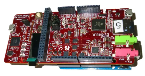
DSP Shield Hardware Description
The DSP Shield is a single-board DSP module designed in the form factor of an Arduino Shield. It is built around the TI TMS320C5517 DSP Core and incorporates several valuable peripherals such as an SD card adapter, OLED display, Audio Codec, and I2C GPIO expanders. These expanders enable the DSP to emulate the GPIO headers typically found on an Arduino board.
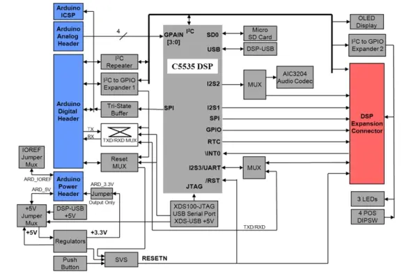
The DSP Shield board incorporates several key hardware components, including:
– TI TMS320C5517 (200MHz) Digital Signal Processor
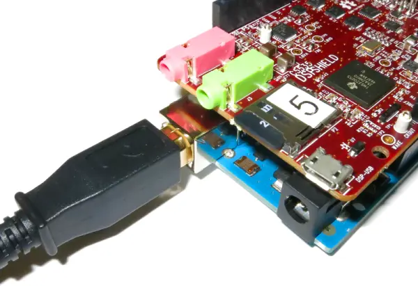
– TI TLV320AIC3204IRGBR Stereo Audio Codec with separate stereo input and output connectors, supporting sample rates up to 96ksps
– Micro SD Card Connector
– USB 2.0 interface for communication with the C5517 DSP
– OLED display with a resolution of 96×16 pixels
– Arduino-compatible header connectors
– Compatibility with Energia software IDE and API for the Arduino interface
– Embedded USB XDS100-V2 JTAG emulator with a secondary serial port
– JTAG compatibility with TI Code Composer Studio software IDE
– Secondary serial port compatibility with Energia software IDE and API
– 40-pin DSP Expansion Connector
– 3 user-controlled LEDs
– 4 user-readable DIP switches
– 1 hardware reset push button switch
– Flexible power sourcing options
Communicating With the DSP Shield
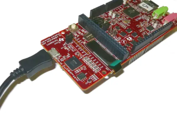
Serial (UART)
The DSP Shield features a Serial port that allows communication with a PC, but it can also be reconfigured for various purposes, including communication with the Arduino. In standalone mode, when the shield is programmed using Energia (as described earlier), the serial port is connected to the USB port on the FTDI XDS-100 chip located next to the OLED display. However, in shield mode, the DSP and Arduino share a Serial bus, and the serial output is visible on the same terminal as the Arduino when it is stacked with the DSP Shield.
SPI
The DSP Shield is equipped with an SPI bus that enables communication with the Arduino. This bus can be programmed directly, similar to how it is done on Arduino, but it can also be interfaced using the ‘Mailbox’ library (accessible here). The ‘Mailbox’ library facilitates bidirectional communication between the DSP Shield and the Arduino. However, it’s important to note that the DSP Shield can only function as an SPI master, while the Arduino must be configured as an SPI slave on this bus.
I2C Bus and GPIO
The DSP Shield features an onboard I2C bus, which facilitates communication with the onboard peripherals such as the GPIO expander chips connected to the Arduino-compatible headers. It is possible to connect the I2C buses of the DSP Shield and Arduino, enabling the Arduino to communicate with the DSP or directly control the peripherals on the DSP Shield, including the Audio Codec and OLED Display. However, it is strongly recommended that only experts attempt to connect these two I2C spaces.
It is important for all users who write code for the DSP Shield itself (using Energia or Code Composer Studio) to review the brief App. Note DSP-01, which provides crucial information about the behavior of the GPIO and I2C subsystems.
OLED Display
The OLED display on the DSP Shield can be controlled using high-level print statements, similar to serial communication. This allows users to send status information and display messages to the user on the OLED display.
Software Description and Downloads
As mentioned earlier, the DSP Shield is provided with a precompiled binary that enables it to function as an Arduino shield and receive commands from the Arduino to activate fixed function DSP blocks. You can download the binary and its corresponding source code here. To compile this application, you will need the DSP Mailbox library, which can be found here. Additionally, the Arduino libraries required for communication with the DSP Shield can be accessed here and here.
In terms of the Co-processor or Standalone modes, the DSP Shield is compatible with Energia, an Arduino-compatible open-source platform primarily designed to support Texas Instruments’ range of microcontrollers, including DSPs. However, please note that the current version of Energia available at energia.nu does not provide support for the DSP Shield. The plan is to add support for the DSP Shield to the main branch of Energia before December 2014, and this page will be updated accordingly.
To facilitate a user-friendly experience, a robust, Arduino-like interface has been developed for the DSP Shield. This interface allows users to develop and teach a wide range of DSP algorithms efficiently.
Software Documentation
The DSP Shield API is structured to resemble the familiar conventions of the Arduino IDE as closely as possible. This includes using C++ style dot notation for hardware interfaces (e.g., AudioC.begin()) and standard function calls like “digitalWrite(pin)” and “digitalRead(pin)” (refer to App. Note DSP-01 for guidance on utilizing the DSP Shield’s onboard GPIO).
The complete software reference manual for the DSP Shield, which has been generated with Doxygen and incorporates comments contributed by Stanford student Maisy Wiseman, is available here: DSP Shield API Reference Manual.
Additional Software Documentation
The DSP Shield API within Energia was developed by integrating various TI libraries and compilers. Below is a partial list of documents pertaining to these tools. While users operating the DSP Shield in shield mode typically won’t need to consult these documents, and even most users in standalone mode may not require them, having these reference materials available can be beneficial.
Programming The Board
The DSP Shield can be programmed using a serial bootloader, similar to contemporary microcontrollers. The user application is stored on the non-volatile microSD card present on the DSP Shield since the DSP core itself lacks on-chip flash memory. Consequently, programming the DSP Shield can be accomplished indirectly by copying the binary file generated by Energia onto the SD card using a PC. Energia itself generates a binary file in the sketch directory when the verify or upload button is clicked to compile the program.