Summary of DIY Laser People Counter
Summary (under 100 words): A DIY laser people counter uses a VL53L1X time-of-flight sensor and an ESP8266 (WEMOS D1 Mini) to detect people passing a doorway by splitting the sensor cone into two zones. It counts direction via zone transitions, serves a web UI over WiFi, and can be built for under €20 with simple electronics, optional 3D-printed enclosure, and Arduino code. The guide covers theory, conventional counters, hardware assembly, software architecture, and mounting.
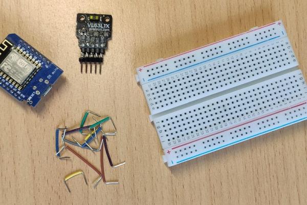
Parts used in the Laser People Counter:
- WEMOS D1 Mini
- VL53L1X ToF Sensor Module
- Small Breadboard
- Jumper wires
- Long Micro USB Cable
- USB Power Brick
- 3D printed enclosure (optional) STL Files
- Soldering iron (tool)
- Laptop with Arduino IDE (tool)
- 3D Printer (optional tool)
Let’s start of with a question: What is a people counter? …. Well, it is a device, that counts the amount of people passing by. They are usually placed in doorways and can be used to see how many people are in a room or a restaurant or a store at any given time.
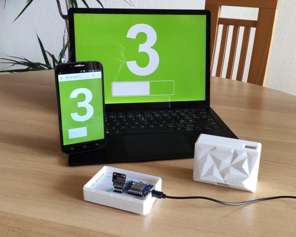
The people counter that I am going to show you today uses a laser to count the people and can be connected to any device that has a webbrowser using WiFi. This allows a simple web UI to be displayed on all kinds of devices as seen in the fifth image. I also attached a little video so you can see it in action.
It is a neat little project, that includes electronics, cool new sensor technology, Arduino programming and even a little bit of 3D printing. And the best part: You can build one yourself for under 20 €.
The backstory
My people counter journey started way back in 2019, when I was working on an unrelated IoT project. I was using a tiny little distance sensor called the VL53L1X (more on that in step 3) and saw a proof of concept video from ST Microelectronics that showed it being used as a people counter. Fast forward to 2020 and we have a global pandemic. One that requires us to social distance. For stores, restaurants, gyms and all other kinds of enclosed public places this means that it is now necessary to limit the amount of people inside. A job for a people counter. I was just waiting for them to appear in any store in no time but that didn’t happen. Here in Germany only a hand full of shops started using electronic people counting systems. The rest placed a person at the store that counts manually.
I was wondering why that is and did a little bit of research. To me it seemed that there were three major reasons:
- Nobody knows that electronic counters exist
- People Counting Systems are too expensive (Especially with a big display for the customers)
- The systems are complicated and require technicians for installation
I remembered the proof of concept from ST which used a really cheap sensor. The demo was very basic and was missing things like a proper user interface but it looked promising. Could that be a better people counter that addresses the above issues?
Fast forward to today and I spent half a year developing a working prototypes and learned a ton of things about people counters.
What you can find in this Instructable
I want to share my knowledge and show you how you can rebuild my latest prototype.
If you want to learn something interesting. If you are looking for a great Internet of Things project, be it for school, university or just a weekend project, you have come to the right place 🙂
I tried to make this Instructable educational, easy to understand and interesting at the same time. If you just want to build your own people counter and don’t care about the theory, you only need 3 steps marked with “Making”. The parts marked with “Theory” give you a lot of extra knowledge but can be skipped.
We are going to start with the theory. I am going to explain how a simple people counter works. We are also going to take a short dive into the different types of people counters that are already available and get a glimpse at how those systems work. Then we are going to get into our laser people counter and all of its inner workings.
Finally we get to the interesting part: Making your own people counter. Which is 3 steps.
- Assemble the Hardware
- Upload the Software
- Connect and mount the counter
In the end we are going to take a look at the weak points and possible improvements that I discovered. As I mentioned, this is still a prototype. It is useful but has a couple of rough edges here and there.
Here is what you need
to build yourself a simple laser people counter
- WEMOS D1 Mini AliExpress | Amazon DE
- VL53L1X ToF Sensor Module AliExpress | Amazon DE
- Small Breadboard AliExpress | Amazon DE
- Jumper wires AliExpress | Amazon DE
- long Micro USB Cable AliExpress | Amazon
- USB Power Brick AliExpress | Amazon
- 3D printed enclosure (optional) STL Files in step 5
Tools:
- Soldering iron
- Laptop with Arduino IDE
- 3D Printer (optional)
Step 1: Theory – How to Count People
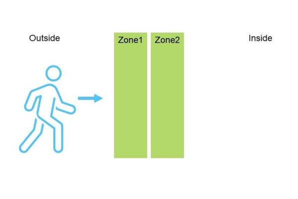
Counting people is not that different from counting objects. We just need to place two detectors in the heading direction of a person as seen in the first image. A detector can be any kind of sensor. For now we just need to know that we have two sensors and that each of them can tell us if a person is present or not. Each sensor checks in a zone, so we have zone 1 and zone 2 that can have a person inside them or not (true or false).
If a person goes from the inside to the outside, our sensors are going to detect it in zone 1, then in zone 2. Once the person has passed our sensors altogether (both sensors return false), we know that someone has entered the room. We then increase our count by one. If this person then decides to leave the room it is going to enter zone 2, then zone 1. If we look at the signals (image 3) you can see that we only need to check for the flanks on entering or leaving the detection zones. The table next to the graph shows all of the possible signal combinations and their counting result. The two lines at the bottom are people that stand in the doorway but then decide to go back so they are neither leaving nor entering (partial entry). I also made a little animation that shows the zone activation when a person enters and leaves the room (attached video).
So that’s it, that is how you count people….. well there are some nuances. A simple people counter, such as the one that I am going to show you today, can only count one person at a time. If there were two people , passing our detection area at the same time, our people counter would get confused.
Multiple people going through the same door are pretty typical in places with wide doors, such as supermarkets. Here you would use a more advanced sensor system, such as a camera, that is mounted above the door (see image 4). Now through some image processing magic, you can detect the heads of people and analyze where they are going. This task is not trivial but can be achieved. Today we are going to focus on the simple counting mechanism and doors that are passed by one person at a time.
Step 2: Theory – Conventional People Counters
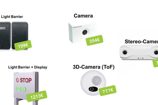
Before we get into the details of how to build our own people counter, lets take a look at the solutions that are available for purchase. I put a couple of them into the image above. There are plenty and they all have their strengths and weaknesses. That’s why I wrote you this little overview.
Light Barrier Counter
Light barriers are the simplest type of counter. They are mounted to the sides of a door, as seen in the second image. Light barrier counters have two light beams, each with their own light sensor. If a person walks through the light beam it doesn’t reach the sensor anymore. Boom, person detected. These types of counters are of the simple type that we discussed in the step before. They can count one person at a time. If there is only one person at a time, they are very reliable and pretty cheap. However the price can quickly increase, if you don’t want a big display for the customers as you can see from the first image.
Normal Cameras
“Normal Cameras” such as the once in your smartphone are the simplest and cheapest way to count multiple people. As mentioned before, counting multiple people is basically counting heads. This is easy if you can clearly distinguish the people from the floor, but that can get tricky if there is bad contrast. Normal cameras are very sensitive to changes in illumination. Those may be caused by sunlight from the outside. It is also very tricky and sometimes impossible, to distinguish a shadow from a person if you can only see a 2D image.
Stereo Cameras
Stereo cameras are like magic to me. They use two cameras spaced apart similar to your eyes. Through some processing magic this gives you a some depth information so you know what is closer (eg. people) and what is farther away (eg. floor with bad contrast). These are some of the most common people counters, as they are fairly reliable. However they can still struggle with bad lighting conditions.
ToF Cameras (true 3D cameras)
Time of Flight (more on that later) cameras don’t rely on colors or visible light. They also don’t need any processing tricks to get depth information. These cameras are true 3D cameras. For every pixel in an image they have a distance. This means that a bunch of people passing below the sensor are seen as a bunch of hills in the 3D image. This technology is very reliable, as it can not be fooled by weird lighting and even works in complete darkness. However, the sensors can be quite expensive and are not that common.
Honorable mentions
The sensors above are the most common but there is a ton of other sensor types available. Some honorable mentions are thermal imaging people counters, camera counters that use facial recognition (good bye privacy) and sensor mats that are placed on the floor. I won’t go into detail about those but they exist.
One thing that is also getting more popular are smartphone counters. They are often referred to as people counters but they are not able to count the exact number of people. They track WiFi and Bluetooth signals and correlate the number of devices that they see with the approximate number of people.
Step 3: Theory – This People Counter
The People Counter, that this Instructable is about, is a little bit different from the ones that are currently available. Mainly because it uses a new Sensor as a people detector.
The Sensor
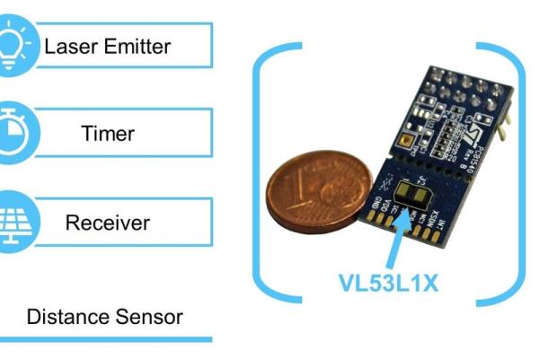
Our Sensor is called the VL53L1X (seen in the first image), which is a fairly boring and complicated name for a very interesting little sensor. A couple of facts about it:
- It can shoot laser beams (invisible and not harmful)
- It can measure the time it takes light to go to an object and come back
- It is very tiny (4.9 mm x 2.5 mm x 1.56 mm)
- You can use it with any Arduino board
- You can get one for under 10€
- You can split its measuring area
The Time of Flight Principle
The sensor is essentially a very fast and very precise distance sensor. It uses the so called Time of Flight principle. I tried to visualize it in the second image. The Sensor consists of an emitter that emits a short pulse of laser lights. It waits for the light to bounce of a surface and return to the sensors receiver. Then it checks how long the light took to come back and uses a simple equation to calculate the distance to the object. It is actually very similar to an ultrasonic sensor, which uses the same equation with the speed of sound instead of the speed of light.
The sensor measures distances inside a cone-like shape (see the third image) with an opening angle of around 27 degrees. This angle is called the Field of View (FOV). However, the sensor does not have to look at the whole cone. The receiver of the VL53L1X is actually an array of 16×16 little light sensors (visualized in the third image). You can use software to tell it to only measure in a certain area of this array. This area is called a Region of Interest (ROI). By using this feature, we can split the cone which gives us two different zones. We can detect a person in each zone by checking if the measured distance is below a certain threshold. And if you read through the second step you already know that we can use this to count people.
Credit where credit is due: I am not the one who came up with this idea. It was the smart folks over at ST Microelectronis, the company that developed and produces the VL53L1X. They implemented a little proof of concept for a people counter back in 2019. You can find their documentation here. I based my people counter design on their concept and gave it a couple of smart upgrades.
Making it Smart
A Sensor that can count people is pretty cool but it is missing a display. We want to display the count on some kind of screen, to make it visible to people entering the store. An easy way of doing this is to use a web-Interface. This allows us to display the count on any device that has a webbrowser, such as a smartphone, a tablet, a laptop or a smart TV. The idea is to connect the sensor and the display device to a WiFi network and have them communicate through that. You can see this concept in the fifth image.
An easy way to create such a “smart” device, that can talk to smartphones, laptops and tvs, is to use a Microcontroller with integrated WiFi capabilities. A microcontroller (MCU) is a little computer that we need to talk to our sensor and do the actual counting. We are going to use the ESP8266 as it can do just that and also includes WiFi and can act as a little webserver, serving websites to other devices. It is also Arduino compatible, which makes it super convenient to program and allows us to use a bunch of great libraries for the sensor and the webserver part.
A More Detailed Look at the software
Our sensor, our microcontroller and webbrowsers are great pieces of technology, but they will not be counting people if we don’t tell them how to do it. Thats why I created a bunch of code. This part is fairly complicated, especially if you are a beginner but I did my best to simplify. The text files that make up my code are pretty boring to look at, that’s why I tried to visualize it in the last image.
You can think of it as a stack of software components talking to each other and to certain hardware components. At the bottom we have our VL53L1X sensor. It talks to our microcontroller board through a the so called I2C bus which is just two wires that carry data and signals. Inside the microcontroller is the first software component, a sensor library that takes care of all of the sensor communication. It reduces the bits and bytes going over the bus to simple functions, such as startMeasurement() and getResult(). I put a second layer of code above that. This second layer abstracts all of the specific sensor functions and reduces it further to three simple pieces of information
- is a person in zone 1 ?
- is a person in zone 2 ?
- does the sensor have new data ?
This abstraction opens the possibility of playing around with different sensors. You could replace my ToF-Sensor code with your own code to use two ultrasonic sensors or two light barriers or two switches to detect a person. This way you can build a different kind of people counter but keep all of the user interface code.
The third layer of code implements our people counting algorithm, that we discussed in the second step.
Above all of that, we have the web UI code. If a display device want’s to display our count, it uses the HTTP protocol to send a request to the ESP8266 webserver. In the web UI code I define what the people counter should send as a response. I told it to send a simple HTML website. The website also has a little bit of JavaScript that opens a permanent connection to the server, a WebSocket, to update the count whenever something changes.
That is basically it. It was a lot of information but now you know what goes on under the hood of this people counter. Time to build your own.
Step 4: Making – Assembling the Hardware
We are going to start with the hardware. This is quite simple, as my design is just a breadboard inside an optional 3D printed enclosure. Considering that, I think that it actually looks pretty good.
Preparing the Boards
Before you can put your microcontroller board and your sensor board onto the breadboard, you have to solder the pins onto them. These should come with the boards themselves.
My sensor board was pretty long and I made it even longer by soldering long header pins to it. This way the sensor itself (the tiny chip with the two bronze colored windows) is further away from the breadboard, so that the cone shaped detection zones don’t interfere with the wall above the door. If you use a different sensor board, make sure to use long pins or wires to make the sensor sit around 26mm above the breadboard (see image 2).
Connecting the Components
I drew wiring diagram which you can see in the third image. You just need to make the following four connections.
Microcontroller <=> Sensor
- 3V3 <=> VCC
- GND <=> GND
- D1 (GPIO5) <=> SCL D2 (GPIO4) SDA
Use small wires to get clean breadboard connections as seen in the fourth image. Make sure to double, tripple and quadrouple check any connection. Even though this setup is quite simple one wrong connection can turn your fun weekend project into a puff of smoke (I’m talking from experience).
Making an Enclosure
You don’t need an enclosure for our people counter, you could just tape the breadboard to the wall and you’ll be good to go. However an enclosure makes it look much more pleasing. I had good experiences in the past with buying cheap lunch boxes and using them as an enclosure.
Since I got a 3D printer I love to make my own enclosures and I also designed one for the people counter that you can download and print yourself. It fits the little breadboard and has a cutout for the sensors detection cone as well as the micro USB cable. It it also has a nice looking low poly front design and the top and bottom pieces are put together by snapping in place.
I printed it in white PLA with 0.2mm layer height, 20% infill on my Anet A8. Make sure to print the top of the enclosure at a 135 degree angle as shown in the last image. This way the low poly surface looks best.
Source: DIY Laser People Counter
- What is a people counter?
A device that counts the amount of people passing by, usually placed in doorways to show how many people are in a room, restaurant, or store. - How does this people counter detect people?
It uses a VL53L1X time-of-flight laser distance sensor split into two regions of interest; detecting zone transitions indicates a person passing. - Can the people counter display the count on common devices?
Yes, it serves a web UI over WiFi from the ESP8266 so any device with a web browser can display the count. - What microcontroller is used in the project?
The project uses an ESP8266-based WEMOS D1 Mini which includes WiFi and is Arduino compatible. - How many sensors are needed for this design?
Only one VL53L1X sensor is used, with its field of view split into two detection zones via ROI. - Do I need to 3D print an enclosure?
No, the enclosure is optional; the project can run with the breadboard taped to the wall, though a 3D printed case is provided for better appearance. - How much does it cost to build?
The author states you can build the people counter for under 20 €. - Can this simple counter handle multiple people passing simultaneously?
No, the simple two-zone approach can count only one person at a time and will be confused by simultaneous passes.