Step 1: COMPONENTS REQUIRED
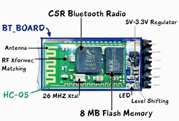
- Bluetooth module (HC-05)
- AT89S52/C51/S51/C52 microcontroller
- Relay Driver ULN2003A
- Relay
- Resistances and capacitors as circuit diagram depicts(below)
- power module(if the input is more than 5V or else not necessary)
- IC 7805(5V voltage regulator)
- 1000uF capacitor
- 10uF capacitor
- led and resistance(as per convenience so that led doesn’t get damaged)
IMPORTANT NOTE: USE 11.0592MHz crystal oscillator as this only gives a baud rate of 9600 same as bluetooth module. So to establish communication between microcontroller and HC-05 we need to match their baud rate just like “WALKIE-TALKIE frequency”)
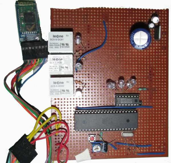
Step 2: CIRCUIT DESIGN
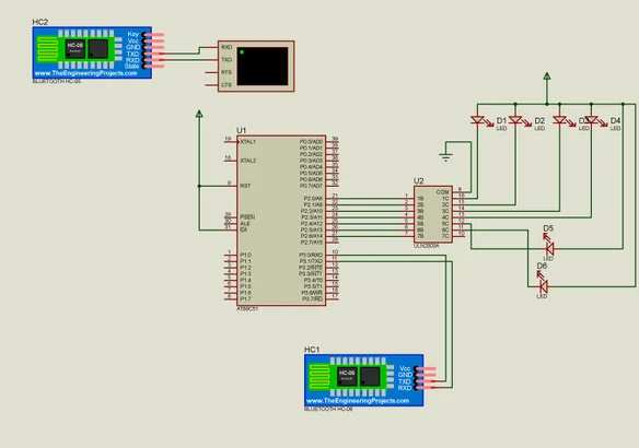
The circuit diagram is as given above. This circuit can be improvised like :-
- the reset circuitry can be omitted if want to do reset through code.
- The 5V power supply circuit can be omitted if you have a 5V standard source.
- Relay of 6V can be used but the +ve pin should be connected through 6V supply.
- Relay driver IC acts as a NOT gate i.e. when signal from microcontroller comes to it, the output of ULN2003 is 0V, initially it’s active high. More bits of microcontroller port i.e. P2 port’s bit(e.g. P2.0,P2.1,P2.2-P2.7) can be connected to remaining ULN2003 IC input pins thus respective output can be obtained.
- Include P3 port with another UNL2003 IC.
- After circuit design the main thing on which the circuit will operate is the CODE that says on which signal which port will be 1 or 0!!!
Step 3: CIRCUIT EXPLANATION
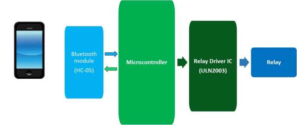
The basic is very simple…
- You need a bluetooth enable host device i.e. mobile,computer or anything!! For the sending of command to the circuit.
- We have used a bluetooth module(HC-05 “HANDS & LEGS OF THE CIRCUIT” ) for catching the signal from paired host device and relaying the same to the microcontroller through its Tx pin to TxD of the later. But you can also use HC-06/07, Sable-x-R2, TIWI-uB1 etc.
- Now comes the microcontroller…”HEART & BARIN OF THE CIRCUIT”… receives data from bluetooth module and does the work according to the code written in it and REPLIES to the bluetooth module.(TxD to Rx)
- Pins of microcontroller gives output and thus connected pins of ULN2003 receives it and gives 0V(initially 5V) making the relay trip(work).
- Relay’s one leg connected to 5V(OR 6V) and another leg get 5V or 0V depending on ULN2003 output. When potential difference(voltage) across relay is 6V it works for 0-3V it doesn’t work.
BE CALM & INNOVATE & MAKE CIRCUITS…
The next edition of this circuit is wifi enabled, IOTs working on it.
THANKS TO INSTRUCTABLES
Step 4: CODE
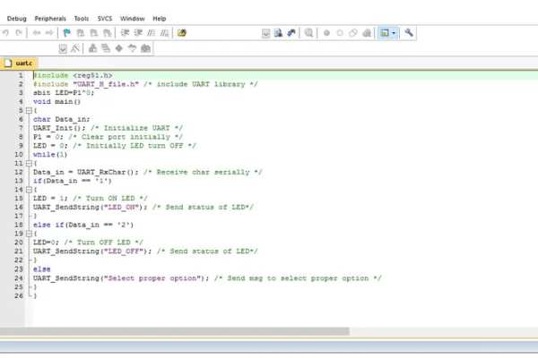
I have written the code in embedded C format in Keil uVision… for the code email me…(abhrodeepc07@gmail.com) I HAVE GIVEN THE PROTOTYPE OF THE CODE IN THE ABOVE PICTURE YOU CAN INNOVATE AND MAKE IT EITHER… WRITE PROGRAM>>SAVE IT IN “*FILENAME*.C” FORMAT>>BUILD>>GET HEX FILE>> AND UPLOAD…
I uploaded the HEX file to the AT89S52 microcontroller referencing to https://www.instructables.com/id/ARDUINO-AS-A-8051…
AGAIN THANKS TO INSTRUCTABLES… If any problem regarding this project contact me!!
CODE: C code for this project
Step 5: ANDROID APP
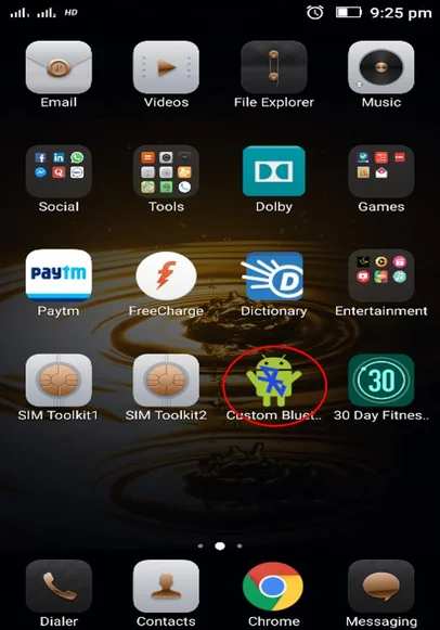
Snapshots are self explanatory… The application name is “Custom Bluetooth App”, which can be downloaded from internet. This can be customized from setup button according to command and respective output through microcontroller. Used “SPP bluetooth” app in video reference(downloadable from google play store)