Summary of DC Motor Speed Control Using Arduino & PWM
This DIY project enables DC motor speed control via a PC interface using an Arduino Nano. Commands are sent through the Serial Monitor, where values 0 to 9 adjust the motor's speed from off to maximum. The system utilizes Pulse Width Modulation (PWM) to simulate analog output, with a 2N2222 transistor acting as a switch to handle the motor's higher current requirements. A diode protects the circuit from reverse current, and a 12V power adapter supplies energy.
Parts used in the Speed Control of DC Motor with PC Interface:
- Arduino Nano
- Low Power DC Motor
- Transistor 2N222
- 12 Volt Power Adapter
- 1K Resistance
- Diode 1N4004
- USB Cable for Arduino Nano
Speed control of DC motor with PC Interface is an easy DIY project. In this project DC motor’s speed is controlled by sending the command through PC. Arduino is directly connected to PC through the USB cable and command is given to Arduino on serial monitor of the Arduino IDE.
Motor is connected to a transistor, and the base of transistor is connected to PWM pin of Arduino and motors speed is varied according to PWM signal coming from Arduino.
Arduino DC Motor Control – Working
Arduino is connected to PC through the USB cable. We can send the command to PC on the serial monitor. We can change the speed of motor from 0 to 9. When 0 is sent over the Serial Monitor, the motor runs at minimum speed (that is zero). When the speed is varied from 1 to 9, the speed increases, with the value 9 set as the maximum speed of the motor.
A PWM DC motor controller technology is used to control the speed. In PWM, the Arduino sends a pulsating wave that is similar to astable mode of 555 timer IC.
PWM Speed Control (Pulse Width Modulation)
Microcontroller and Arduino are digital devices; they cannot give the analog output. Microcontroller gives Zero and ONE as output, where ZERO is logical LOW and ONE is logical HIGH. In our case, we are using 5 volt version of the Arduino. So it’s logical ZERO is zero voltage, and logical HIGH is 5 voltage.
Digital output is good for digital devices but sometimes we need the analog output. In such a case the PWM is very useful. In the PWM, output signal switches between zero and one, on high and fixed frequency, as shown in the figure below.
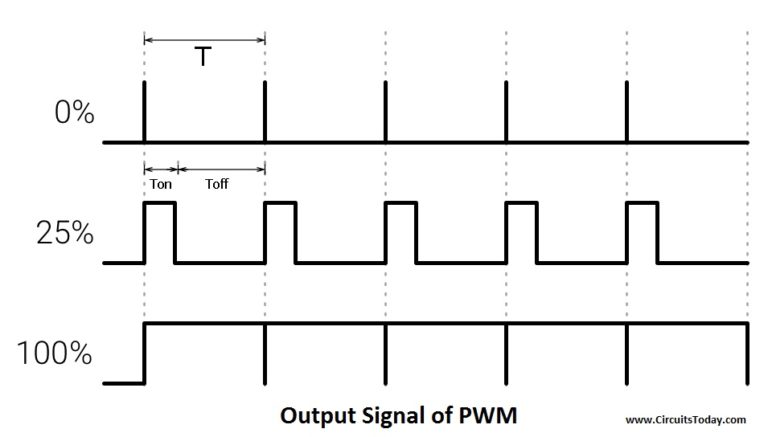
As shown in the above figure the ON time is “Ton” and the OFF time is “Toff”. T is the sum of the “Ton” and “Toff” which is called the Time Period. In the concept of PWM “T” is not varying and the “Ton” and the “Toff” can vary, in this way when “Ton” increase “Toff” will decrease and “Toff” increase when “Ton” decrease proportionally.
The duty cycle is the fraction of one Time period. Duty cycle is commonly expressed as a percentage or a ratio. A period is the time it takes for a signal to complete an on-and-off cycle. As a formula, a duty cycle may be expressed as:
DUTY CYCLE = (Ton ÷ T) x100 %
Now the motor’s speed varies according to duty cycle. Suppose the duty is zero, motor does not run and when duty cycle is 100 % the motor moves on maximum RPM. But this concept is not always right because motor starts running after giving some fixed voltage that is called threshold voltage.
Transistor (2N2222)
Microcontroller and the Arduino can process signals and consumes almost 20 to 40mA current but motors need high current and voltage, so we are using the transistor for driving the motor. Transistor is connected in series with motor and transistor’s base is connected to Arduino’s PWM pin through a resistance. PWM signal is coming from Arduino and the transistor works as a switch and it short circuit the Emitter (E) and Collector (C) when PWM signal is in High state and normally opens when PWM signal is in LOW state. This process works continuously and the motors runs at desired speed.
Components
| Components | Specification | Quantity |
|---|---|---|
| Arduino | Nano | 1 |
| DC Motor | Low Power | 1 |
| Transistor | 2N222 | 1 |
| Power Adapter | 12 Volts | 1 |
| Resistance | 1K | 1 |
| Diode | 1N4004 | 1 |
| USB Cable | For Arduino Nano | 1 |
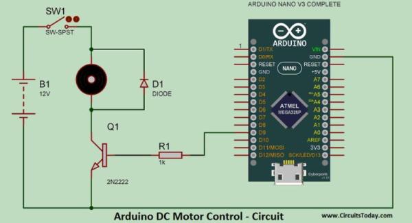
Arduino DC Motor Control – Circuit
Circuit diagram is shown in the figure below. If you are making this circuit on the general purpose PCB (ZERO PCB) or breadboard, this figure is useful.
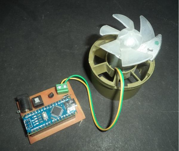
Arduino DC Motor Speed Control
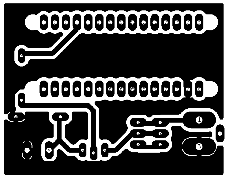
Moreover, if you are good in the PCB Etching, use the images provided below.
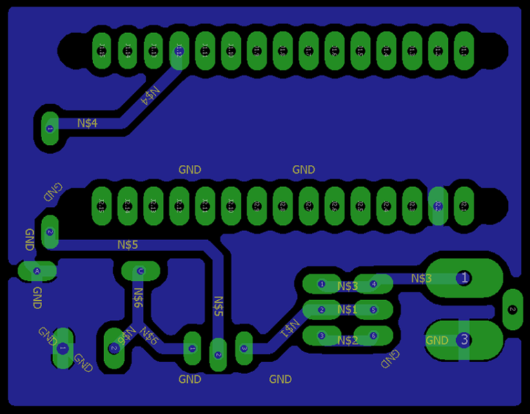
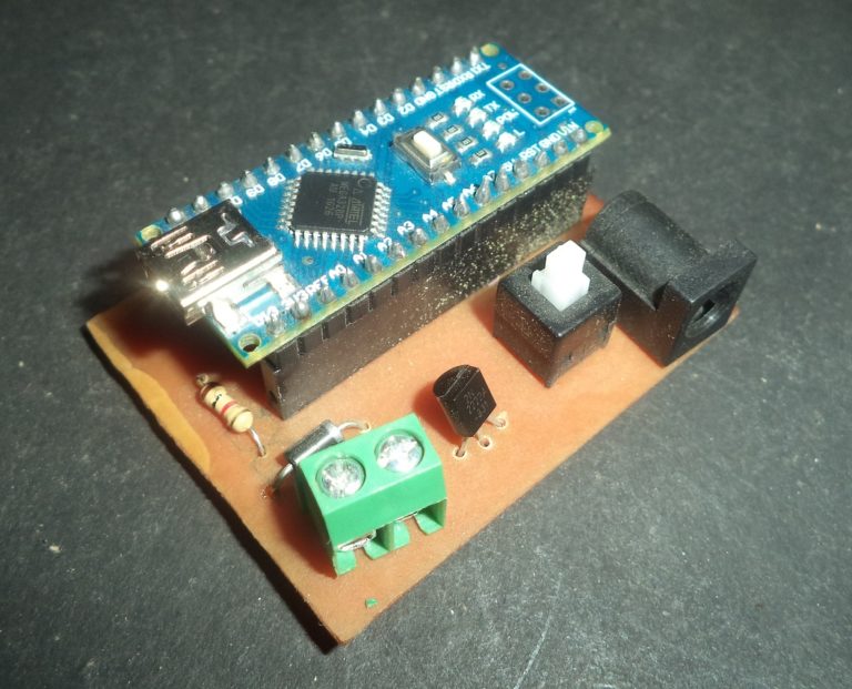
Arduino-PWM DC Motor Control – PCB Design
Speed Control of DC Motor
In the circuit an Arduino Nano is used, which is very small in size and Breadboard friendly.
A transistor’s (2n2222) BASE pin is connected to D9 pin of Arduino through a Resistance of 1k ohm, Resistance is used for current limitation. Motor is connected between collector pin of transistor and Vcc. A diode (1n4004) is connected parallel to the motor in reverse bias; it is used for blocking the reverse current. Emitter pin of the transistor is connected to the ground. This circuit is powered by a 12 volt adapter.
Arduino PWM Motor Control – Video
Arduino DC Motor Control
Arduino PWM Motor Control
DC Motor Speed Control – Download Program
In the beginning of the code two integers are declared by name “out1” and “val”, where out1 is equal to 9 which shown that pin D9 of Arduino is used as output pin (or PWM pin). Moreover, data coming from the serial monitor saved in the second integer “val”.
In the void setup() serial communication is begin by using function “Serial.begin(9600)” where 9600 is the baud rate of serial monitor. After it “out1” is declared as output because the motor is an output device.
In the void loop “serial.available” is used inside the “if” condition, it become true when any data is sent over the serial monitor. This data is saved in “val” integer using “Serial.read” function.
After it many “if” conditions are used, in the first “if condition”, when ‘0’ is sent through the serial monitor, it become true. In the bracket “analogWrite(out1 , 0)” is used for running the motor at the zero PWM value. In the function “analogWrite (out1, 0)”, “out1” is used to indicate the pin which we want to use and “0” is the PWM value at this pin. After it “Speed is = 0” is shown on serial monitor using “Serial.println” function. After it the integer “val” is updated to 10, where 10 is the random value, which is other than 0 to 9.
In the next line if condition is used for “val ==1”, at this time motor runs at PWM value of 175. Same conditions are used upto 9, at the 9 motor runs at 255 PWM value, 255 is the maximum PWM value.
Process
- Connect the Arduino through USB and upload the code
- Open the serial monitor and set the baud rate at 9600
- Now type any number from 0 to 9.
After typing any value from zero to 9, speed of the motor varies, but we cannot see varying speed in video properly, but you can see it live.
Source : DC Motor Speed Control Using Arduino & PWM
- How is the motor speed controlled?
The speed is controlled by sending commands from a PC to the Arduino via the Serial Monitor, where values 0 to 9 determine the speed. - What technology is used to vary the motor speed?
Pulse Width Modulation or PWM is used to send pulsating waves that vary the duty cycle to change the motor speed. - Why is a transistor used in this circuit?
A transistor is used because motors require high current and voltage that microcontrollers cannot provide directly; it acts as a switch. - What is the function of the diode in the circuit?
The diode connected in parallel to the motor blocks reverse current to protect the circuit. - Which pin on the Arduino is used for the PWM signal?
Digital pin D9 is used as the output pin to send the PWM signal to the transistor base. - What happens when the value 0 is sent via the Serial Monitor?
When 0 is sent, the motor runs at minimum speed, which effectively means it stops. - What power supply voltage is required for this project?
The circuit is powered by a 12 Volt adapter. - Can the Arduino give a direct analog output?
No, the Arduino is a digital device that gives logical zero and one outputs, so PWM is used to simulate analog behavior.