For those who don’t know Nixie tubes are electronic devices used for displaying numbers and other character using glow discharge.
They date back to 1950s not used commercially anymore. Currently they do experience second life though, as people do tons of cool projects.
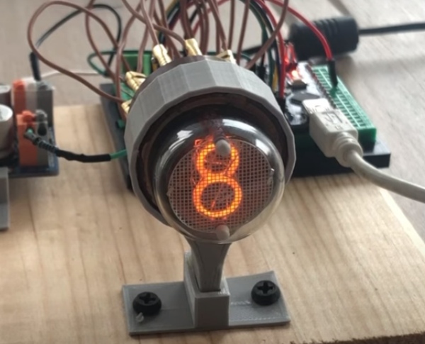
In this instructable I will show you how to glow individual digits with basic connectivity to power source. And then I will also show how to use Arduino microcontroller to control which digit is lit.
Step 1: Nixie Tube Built
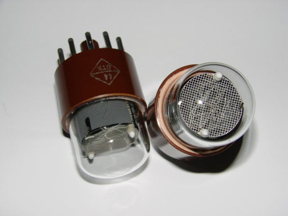
Nixie tubes come in all shapes and forms. The one I will use in this instructable is IN-1 type of tube used to display digits 0 to 9.
Nixie tube IN-1 has 11 pins:
- pins 1-10 are cathodes and pin number corresponds to digit that will lit if electricity flows through that pin (with one exception where pin 10 is linked to digit 0)
- 11th pin is the common anode and should be connected through current limiting resistor. I am using 20k resistor
You can see cathods and an anode on the scan from the old soviet documentation. Funny enough a lot of datasheets for various nixietubes are available as scans of old document , often in cirillic.
Step 2: Powering Nixie Tube
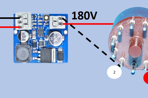
IN-1 tube needs around 180V to work. The boost converter NCH6100HV can provide just that. It boost the 12V input voltage to up to 180V output voltage
DISCLAIMER!!!! Working with high voltage can be dangerous. Please take extreme caution if you plan on using Nixie tubes in your projects.
Here is the diagram of how boost converter should be connected to the nixie tube to power the tube and light up a single digit.
Also you see the photo of the digit 6 being lit by connecting nixie tube anode to 180V and connecting ground to cathode/pin 6 corresponding to digit 6. If you want to lit a different digit you need to connect GND to other pin.
If you connect GND to multiple cathodes, multiple digits would lit.
Step 3: K155ID1 Microchip for Controlling Nixietubes
We can use arduino nano to control which digit would be displayed in the nixie tube. We could do it with 10 digital pins of arduino connected to each cathode of the nixie tube and lighting up digits by providing LOW signal to respective pins. But this is just to control one tube.
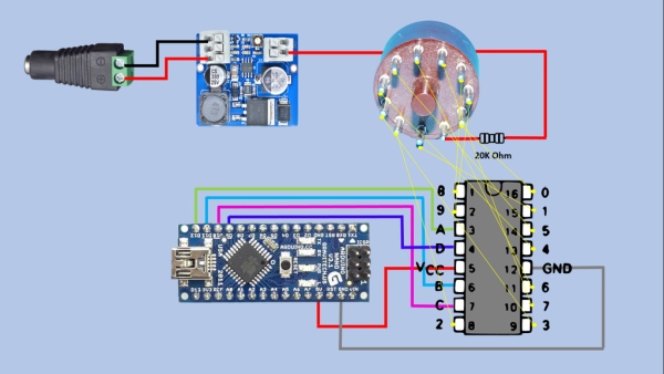
With multiple tubes you are rapidly running out of pins. This is where this K155ID1 microchip comes in handy. It allows to control the nixie tube with just 4 arduino pins.
The chip has 16 legs.
- Ten legs are ground connections, each for one of the 10 cathode pins of the nixie tube .
- Then you also have VCC and ground legs that you would connect to 5v anf ground pins of Arduino.
- And then we are left with the last 4 legs that are connected to 4 digital pins of Arduino. Through those pins the information is passed to the mirochip that indicates which digit should start to glow inside the tube.
Step 4: How Does K155ID1 Work?
So how do we control which nixie tube’s pin would be grounded. The microchip has 4 input legs and 10 output ones.
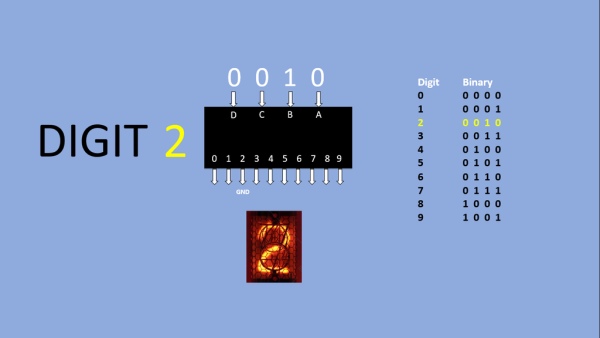
Through those four input pins we pass the binary representation of the digit we want to lit. Here is the table that lists all possible combinations
Digit		Binary

0		0000

1		0001

2		0010

3		0011

4		0100

5		0101

6		0110

7		0111

8		1000

9		1001
In the image you see an example where we want to display digit 2. We pass binary representation of 2 : 0 0 1 0 to four input pins and that grounds second leg of the microchip. If that leg is connected to second pin of nixie tube the digit 2 would glow.
Step 5: Writing Arduino Code
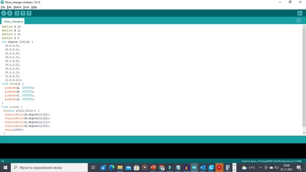
Lets write a simple code that will display all 10 digits in 1 second intervals.
we start with declaring the pins arduino pins connected to input pins of K155ID1 microchip
#define A 12
#define B 11
#define C 10
#define D 9
Then we declare the table with binary representations of each digit
int digits [10][4] {
  {0,0,0,0},
  {0,0,0,1},
  {0,0,1,0},
  {0,0,1,1},
  {0,1,0,0},
  {0,1,0,1},
  {0,1,1,0},
  {0,1,1,1},
  {1,0,0,0},
  {1,0,0,1}};
In setup function we decalare the pins A B C D as output pins
void setup() {

  pinMode(A, OUTPUT);
  pinMode(B, OUTPUT);
  pinMode(C, OUTPUT);
  pinMode(D, OUTPUT);

}
And finally in the main loop we have a fourloop executed 10 times. For each iteration it reads the corresponding row from digits table representing the digit and sending bits of that digit to ABCD pins of arduino.
That results in groubdin corresponding pin of the microchip which in turn sends low signal to the selected cathode of the nixietube causing the digit linked to that cathode to glow.
void loop() {
 for(int i=0;i<10;i++) {
  digitalWrite(A,digits[i][3]);
  digitalWrite(B,digits[i][2]);
  digitalWrite(C,digits[i][1]);
  digitalWrite(D,digits[i][0]);
  delay(1000);
 }
}
Simple . Isin’t it?:)
Step 6: Conclusion
Hope you find this instructable useful.
If you want you can check video version of this isntructable. It provides some more information e.g. it also discusses cathode poisoning , the condition that nixie tubes can suffer from and how this can be prevented.
- First video shows the use of the boost converter and lighting up individual digits by manually connecting GND to indivdual cathodes
- Second video shows the whole process of controlling nixie tube with K155ID1 microchip
If you like this content and you want to support me in creating similar videos go to my Patreon webpage https://www.patreon.com/MariosIdeas
Source: Controlling Nixie Tube With Arduino Using K155ID1 Microchip