For some strange reason I have a fascination with various types of electronic clocks (which explains this article). Therefore this project will be the start of an irregular series of clock projects whose goal will be easy to follow and produce interesting results. Our “Clock One” will use a Freetronics Dot Matrix Display board as reviewed previously. Here is an example of an operating Clock One:
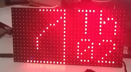
As you can see, on the left half of the board we have a representation of an analogue clock. Considering we only have sixteen rows of sixteen LEDs, it isn’t too bad at all. The seconds are illuminated by sixty pixels that circumnavigate the square clock throughout the minute. On the right we display the first two letters of the day of the week, and below this the date. In the example image above, the time is 6:08. We omitted the month – if you don’t know what month it is you have larger problems.
Software
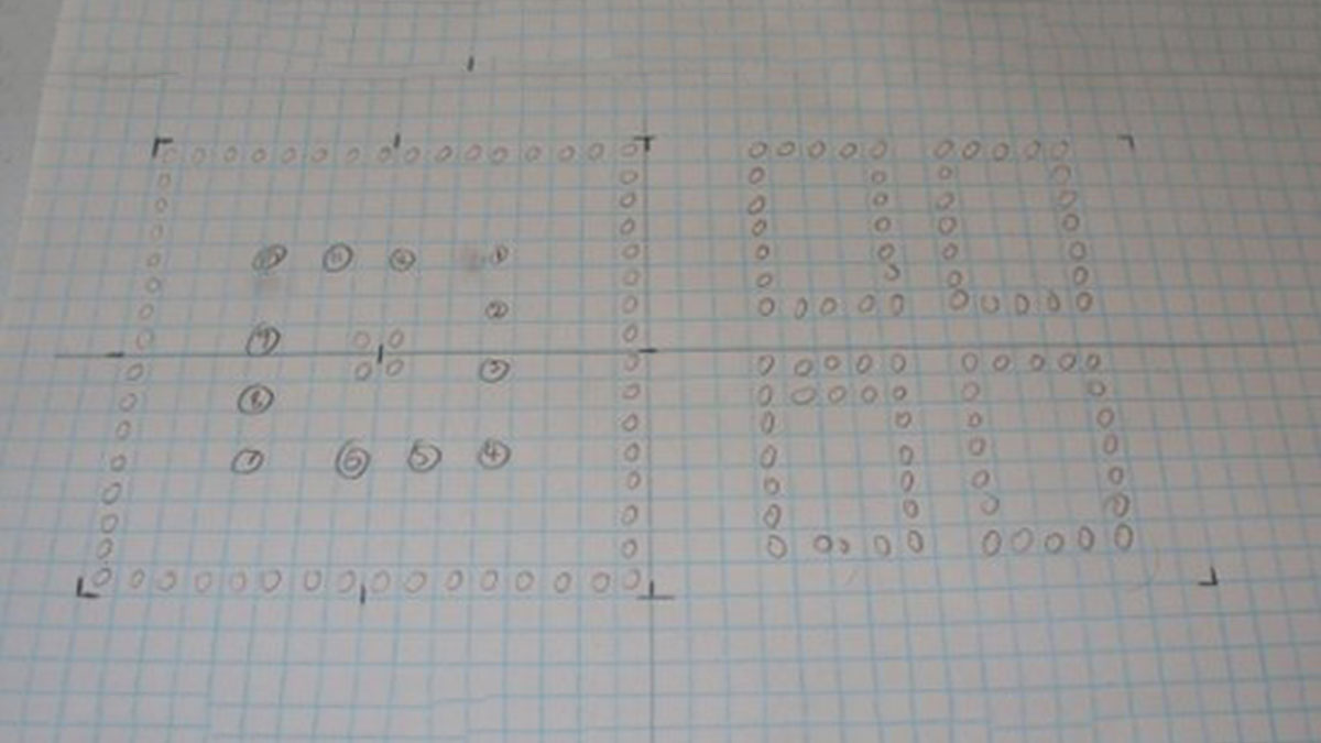
Planning the clock was quite simple. As we can only draw lines, individual pixels, and strings of text or individual characters, some planning was required in order to control the display board. A simple method is to use some graph paper and note down where you want things and the coordinates for each pixel of interest, for example:
[box color=”#985D00″ bg=”#FFF8CB” font=”verdana” fontsize=”14 ” radius=”20 ” border=”#985D12″ float=”right” head=”Major Components in Project” headbg=”#FFEB70″ headcolor=”#985D00″]
Hardware
To make this happen you will need:
- A Freetronics Dot Matrix Display board;
- If you want the run the display at full brightness (ouch!) you will need a 5V 2.8A power supply – however our example is running without the external supply and is pretty strong
- An Arduino board of some sort, an Uno or Eleven is a good start
- A Maxim DS1307 real-time clock IC circuit. How to build this is explained here. If you have a Freetronics board, you can add this circuit directly onto the board!
[/box]
For more detail: Clock One – Digital plus Analog Clock An Arduino