Summary of Calibration
This article explains a sensor calibration technique where an Arduino board records the highest and lowest analog readings during the first five seconds of startup. These values establish the expected range for subsequent loop operations, allowing future sensor data to be accurately mapped to a standard output scale using the `map` function.
Parts used in Sensor Calibration Project:
- Arduino or Genuino board
- LED
- Analog sensor (e.g., photoresistor)
- 10k ohm resistor
- 220 ohm resistor
- Hook-up wires
- Breadboard
This example demonstrates one techinque for calibrating sensor input. The board takes sensor readings for five seconds during the startup, and tracks the highest and lowest values it gets. These sensor readings during the first five seconds of the sketch execution define the minimum and maximum of expected values for the readings taken during the loop.
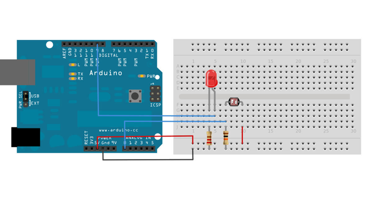
Circuit
Analog sensor (e.g. potentiometer, light sensor) on Analog input 2. LED on Digital pin 9.
Hardware Required
- Arduino or Genuino board
- LED
- analog sensor (a photoresistor will do)
- 10k ohm resistor
- 220 ohm resistor
- hook-up wires
- breadboard
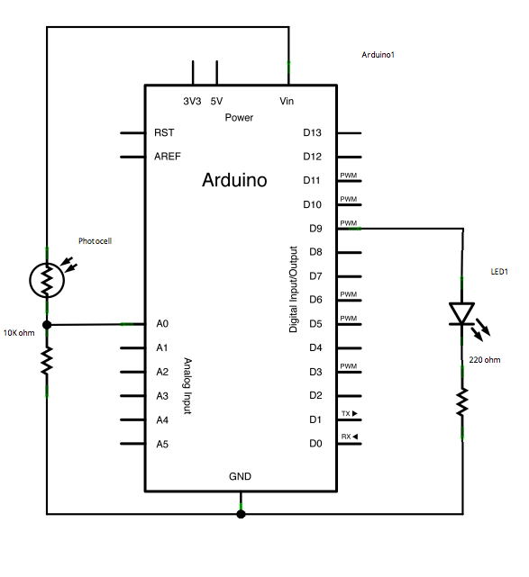
Connect an LED to digital pin 9 with a 220 ohm current limiting resistor in series. Connect a photoresistor to 5V and then to analog pin 0 with a 10K ohm resistor to ground.
Schematic
Before the setup, you set initial values for the minimum and maximum like so:
int sensorMin = 1023;        // minimum sensor value
int sensorMax = 0;           // maximum sensor value
These may seem backwards. Initially, you set the minimum high and read for anything lower than that, saving it as the new minimum. Likewise, you set the maximum low and read for anything higher as the new maximum, like so:
// calibrate during the first five seconds
 while (millis() < 5000) {
   sensorValue = analogRead(sensorPin);

   // record the maximum sensor value
   if (sensorValue > sensorMax) {
     sensorMax = sensorValue;
   }
   // record the minimum sensor value
   if (sensorValue < sensorMin) {
     sensorMin = sensorValue;
   }
 }
This way, any further readings you take can be mapped to the range between this minimum and maximum like so:
// apply the calibration to the sensor reading
sensorValue = map(sensorValue, sensorMin, sensorMax, 0, 255);
Here’s the whole program:
For More Detail: Calibration
- How long does the board take sensor readings during startup?
The board takes sensor readings for five seconds during the startup. - What pins are used for the analog sensor and LED?
The analog sensor connects to Analog input 2 and the LED connects to Digital pin 9. - Does the code initialize the minimum value to zero?
No, the code initializes the minimum value to 1023 so it can record any lower value found. - Can I use a potentiometer instead of a photoresistor?
Yes, the text states an analog sensor like a potentiometer or light sensor works on Analog input 2. - What is the best way to map the calibrated sensor reading?
You apply the calibration by mapping the sensor value from the recorded min and max to the range 0 to 255. - How do you connect the photoresistor in the circuit?
You connect the photoresistor to 5V and then to analog pin 0 with a 10K ohm resistor to ground. - Why set the initial maximum value to zero?
You set the maximum low initially to read for anything higher as the new maximum. - What happens after the five-second calibration period ends?
Any further readings taken during the loop are mapped to the range between the recorded minimum and maximum. - Is a current limiting resistor required for the LED?
Yes, you must connect an LED to digital pin 9 with a 220 ohm current limiting resistor in series. - Which variable stores the highest sensor value found?
The variable named sensorMax stores the highest sensor value found during the calibration loop.