Summary of How to Build a LM35 Temperature Sensor Circuit
This project demonstrates building a temperature sensor circuit using an LM35 IC and an Arduino board. The circuit reads ambient temperature, converting the analog voltage output into degrees Celsius and Fahrenheit, which are displayed on a computer via the Arduino Serial Monitor.
Parts used in the LM35 Temperature Sensor Circuit:
- Arduino Board
- LM35 Temperature Sensor IC
- Computer
- USB cable with Type A and B connectors
In this project, we will demonstrate how to build temperature sensor circuit using a LM35 sensor.
As a temperature sensor, the circuit will read the temperature of the surrounding environment and relay thi temperature to us back in degrees celsius.
The IC we will use to measure the temperature is the LM35 IC. We will integrate this with the arduino to measure the temperature. The arduino will then read this measured value from the LM35 and translate into degrees fahrenheit and celsius, which we will be able to read from the computer from the arduino serial monitor.
Components Needed to Build the LM35 Temperature Sensor Circuit
- Arduino Board
- LM35 Temperature Sensor IC
- Computer
- USB with type A and B connectors
We can use any type of arduino board.
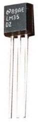
The LM35 is a low voltage IC which uses approximately +5VDC of power. This is ideal because the arduino’s power pin gives out 5V of power. The IC has just 3 pins, 2 for the power supply and one for the analog output.
The output pin provides an analog voltage output that is linearly proportional to the celsius (centigrade) temperature. Pin 2 gives an output of 1 millivolt per 0.1°C (10mV per degree). oSo to get the degree value in celsius, all that must be done is to take the voltage output and divide it by 10- this give out the value degrees in celsius.
So, for example, if the output pin, pin 2, gives out a value of 315mV (0.315V), this is equivalent to a temperature of 31.5°C.
We can then easily convert this celsius value into fahrenheit by plugging in the appropriate conversion equation. All we must do is write this code and upload it to the arduino to convert this celsius temperature into fahrenheit. The code is shown below.
Below is the pinout of the LM35 IC:
Pin 1 receives positive DC voltage in order for the IC to work. This, again, is voltage approximately 5 volts. Pin 3 is the ground, so it receives the ground or negative terminal of the DC power supply. And Pin 2 is the output of the IC, outputting an analog voltage in porportion to the temperature it measures.
This is the datasheet of the LM35 IC: LM35 Temperature Sensor IC Datasheet.
The arduino, with suitable code, can then interpret this measured analog voltage and output to us the temperature in degrees celsius and fahrenheit.
Also to do this project we need a USB cable with a Type A connector on one end and a Type B connector on the other end. This is so that we can hook our arduino to a computer and send it code that it can run to display to us the temperature.
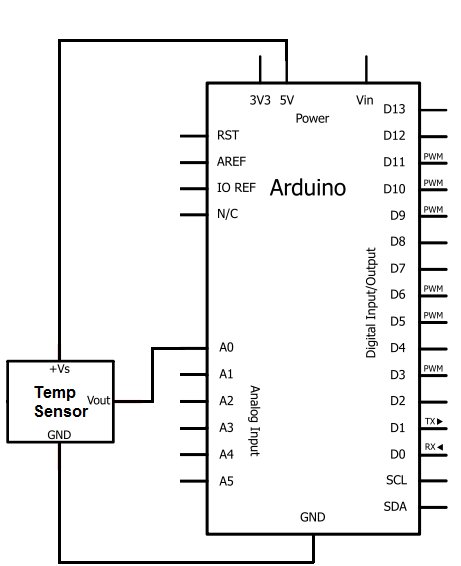
Temperature Sensor Circuit Schematic
The temperature sensor circuit we will build is shown below:
For more detail: How to Build a LM35 Temperature Sensor Circuit
- How does the LM35 sensor calculate temperature?
The sensor outputs an analog voltage linearly proportional to Celsius temperature, where 10mV equals one degree. - Can I use any type of Arduino board for this project?
Yes, you can use any type of Arduino board to build this circuit. - What voltage does the LM35 IC require to operate?
The LM35 is a low voltage IC that uses approximately +5VDC of power. - How do I convert the LM35 voltage output to degrees Celsius?
You must take the voltage output and divide it by 10 to get the value in degrees Celsius. - Which pin on the LM35 provides the temperature data?
Pin 2 is the output pin that provides an analog voltage proportional to the measured temperature. - What is the function of Pin 1 on the LM35 IC?
Pin 1 receives positive DC voltage, approximately 5 volts, to allow the IC to work. - How can I view the temperature readings from the circuit?
The Arduino translates the values and displays them in degrees Celsius and Fahrenheit on the computer serial monitor. - What type of USB cable is needed for this project?
You need a USB cable with a Type A connector on one end and a Type B connector on the other.