
Summary of How to Build an Arduino Circuit on a Breadboard
This article guides users in assembling a compact, functional Arduino circuit on a breadboard using Jameco's Barebones Kit. It details the necessary components, including an ATmega328P microcontroller, voltage regulators, capacitors, resistors, LEDs, and a crystal oscillator. The guide explains how to connect power supply elements like 9V batteries or adapters, integrate the 7805T regulator for 5V conversion, and wire up the LED indicators and decoupling capacitors to ensure stable operation without damaging the IC.
Parts used in the Barebones Arduino Circuit:
- IC, ATmega328P
- Socket, IC, 28-pin, 0.3"
- IC, 5V Regulator, 7805T
- LED, Red, 660nm, T1-3/4
- LED, Green, 565nm, T1-3/4
- Resistor, 1/4W, 10KΩ
- Resistor, 1/4W, 180Ω
- Capacitor, radial, 10µF, 50V
- Crystal, 16MHz, low-profile
- Capacitor, ceramic disc, 22pF, 50V
- Capacitor, ceramic disc, 0.1µF, 50V
- Switch, pushbutton, OFF-(ON)
- Header, 6-pin, 1 row, vertical, 0.1"
- IC, 3.3V Regulator, LM1117T-3.3
- Capacitor, tantalum, 10µF, 25V
- Wire, Hook-up, 22 AWG solid
- Wire Jumper kit, 22AWG
- Breadboard, 830 point
- FTDI Breakout board, 5V, USB to Serial
- Power Supply, Wall adapter, 9V @ 1.2A
- DC Power Jack, 2.1mm
- Battery holder w/ cover & switch, 9V
- Battery, Energizer 9V
Small Kit with Big Functionality
By Ryan Winters
Product Manager
There are many reasons to build your own Arduino circuit on a breadboard or PCB. It takes less space, projects don’t always require every pin to be used on the I/O headers, or maybe you won’t be using a shield but you still want Arduino as the brain of your project. The following steps will outline how to assemble the circuit on a breadboard. I am borrowing the majority of the walk-through from the Arduino site and recommend you purchase Jameco’s Barebones Arduino Circuit Kit. You can order the components separately or save a little money by ordering this kit. The breadboard is not included in the kit.
This Kit Includes:
| Qty. | Part Description | Mfr. Part No. |
| 1 | IC, ATmega328P | A000048 |
| 1 | Socket, IC, 28-pin, 0.3″ | 390261-9 |
| 1 | IC, 5V Regulator, 7805T | 7805T |
| 1 | LED, Red, 660nm, T1-3/4 | UT1871-81-M1-R |
| 1 | LED, Green, 565nm, T1-3/4 | MCDL-5013GD |
| 1 | Resistor, 1/4W, 10KΩ | CF1/4W103JRC |
| 2 | Resistor, 1/4W, 180Ω | CF1/4W181JRC |
| 2 | Capacitor, radial, 10µF, 50V | R10/50 |
| 1 | Crystal, 16MHz, low-profile | TQR49S16M0000A2010 |
| 2 | Capacitor, ceramic disc, 22pF, 50V | DC22 |
| 1 | Capacitor, ceramic disc, 0.1µF, 50V | DC.1 |
| 1 | Switch, pushbutton, OFF-(ON) | TL1105-A |
| 1 | Header, 6-pin, 1 row, vertical, 0.1″ | JS1109-6-R |
| 1 | IC, 3.3V Regulator, LM1117T-3.3 | LM1117T-3.3/LD1117V33 |
| 2 | Capacitor, tantalum, 10µF, 25V | TM10/25 |
Other components you may need:
| Qty. | Part Description | Mfr. Part No. |
| 1 | Wire, Hook-up, 22 AWG solid, 100′, Blue | 9313-LB-R |
| 1 | Wire Jumper kit, 22AWG, 70pcs, 14 lengths, pre-stripped | WJW-70B-5 |
| 1 | Breadboard, 830 point, 6.5″ x 2.125 | WBU-202-R |
| 1 | FTDI Breakout board, 5V, USB to Serial | 50512 |
| 1 | Power Supply, Wall adapter, 9V @ 1.2A | S15AD090150H0650-R |
| 1 | DC Power Jack, 2.1mm | 722A |
| 1 | Battery holder w/ cover & switch, 9V, 6″ wires | SBH-9VAS |
| 1 | Battery, Energizer 9V | ALK 9V 522 |
Step 1: Parts Inventory
Start by laying out the pieces in your kit.
Step 2: Add Power Supply Components
The Arduino power jack can accept an input voltage range of 7 to 16 volts. The most common input sources are a trusty 9V battery or a 9-12VDC power supply. Because most sensors and chips require a 5V source, we will need the 7805T voltage regulator to cut the 9V down to a component friendly 5V. If you connect more than 16V, you risk damaging the IC.
A. Add the power and ground jumper wires where the voltage regulator will be as shown below.
B. Next, add power and ground wires at the bottom of the breadboard to connect the ground rails and the power rails together as pictured.
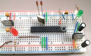
C. The 7805 voltage regulator is a TO-220 package. The positive input from the external power source will connect with the component facing you (printed side) and the leads pointing down the first pin (left side). The middle pin is ground (negative) and the third pin (right side) is the 5V output side. Add wires to connect the output side of the regulator to the power rail of the breadboard and the ground to the ground rail.
D. Add the 10µF decoupling capacitors between the input power and ground, and also on the output side between the power rail and the ground rail. The capacitors are polarized; the negative side goes to ground and the other pin goes to the positive voltage.
E. Place the power LED close to the input source and at the top of the breadboard. You can use the green or red LED. Connect a jumper wire from the negative lead (short leg) of the LED to the ground rail and install a 180Ω resistor from the positive LED lead (long leg) to the power rail.
For more detail: How to Build an Arduino Circuit on a Breadboard
-
Why build your own Arduino circuit on a breadboard?
It takes less space, projects do not always require every pin on I/O headers, and you can use Arduino as the brain without a shield. -
What is the recommended kit for this project?
Jameco's Barebones Arduino Circuit Kit is recommended, though components can be ordered separately. -
What input voltage range does the Arduino power jack accept?
The power jack accepts an input voltage range of 7 to 16 volts. -
Which component is used to convert 9V down to 5V?
The 7805T voltage regulator is used to cut the 9V down to a component friendly 5V source. -
How should the 7805T voltage regulator pins be oriented?
The positive input connects to the first pin (left side) with the printed side facing you and leads pointing down; the middle pin is ground and the third pin is the 5V output. -
How are the polarized decoupling capacitors connected?
The negative side goes to ground and the other pin goes to the positive voltage. -
What happens if you connect more than 16V to the circuit?
You risk damaging the IC. -
How do you identify the positive and negative legs of an LED?
The long leg is the positive lead and the short leg is the negative lead.
