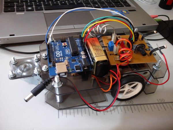
Summary of BUGBot – Light Follower Robot using Arduino
This article outlines the design of a light-following robot called BUGBot, which uses an Arduino as its central controller. The system relies on two Light Dependent Resistors (LDRs) to detect light direction and DC motors with a gearbox to execute movement. By analyzing light intensity on the sensors, the Arduino logic determines whether the robot should move forward, turn left, turn right, or stop. The motor driver circuit utilizes Darlington transistors rather than an H-bridge to ensure unidirectional rotation based on sensor input.
Parts used in the BUGBot:
- Arduino
- 2 x LDR sensors
- DC motors
- Tamyia GearBox (58:1 ratio)
- 2 x TIP120 transistors
- 2 x 1N4001 Diodes
- 2 x 3mm green LEDs
- 2 x 1KΩ resistors
- 10K potentiometer
The figures above shows the basic idea of any robot, where we have some inputs and output devices connected to the brain and some outputs controlled by the brain. In our case we will have the Arduino like the brain.
The central Brain, controls all movements of the Robot. The sensors will do the monitoring where the light focus is and finally the motors that gives to the robot its movements to go forward, to turn left and to turn right.
The input devices will be LDRs (Light Dependent Resistor) those components have its resistance changed according to the incidence of light on the device. Basically, if there is no incident light, the LDR will have a high resistance (from 200KΩ to 5MΩ more or less), and when the incidence of light the LDR will have a reduced resistance (since some dozens of ohms to rough a few hundreds) as we can see in the LDR’s characteristic curve above
A LDR is also sensitive to the wavelength of the incident light, so we can say that it depends on the color of the light.
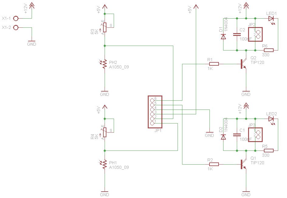
Step 1: Basic Circuit
In the figure above, we can see the basic circuit for driving an LED using a LDR as light sensor.
In the circuit on the left, initially we can note that the LED is off because the resistance of the LDR without incident light, let the transistor in cut state. When we line up the light focus on the LDR, it will decrease its resistance and thus we have a base polarization, and so the transistor enter in the conducting state, switching the LED on.
In the circuit on the right, we will notice that the LED is initially in the state on, since we have no incident light on the LDR and the LDR have a resistance greater than the sum of resistances of the resistor of 10K + the 10K potentiometer; the transistor base will be polarized driving the LED, and when the light falls on the LDR, the LDR will have a decrease in current and will sustain the transistor into the cut state switching the LED off.
A sensitivity setting in the system is allowed through the 10K potentiometer.
Naturally, we can use the LDR in another way, but this is the most usual form.
Step 2: BUGBot Basics
The robot has two LDR sensors in order to determine if he should move to the right, left, forward, or remain stationary.
1 x LDR sensor RIGHT
1 x LDR sensor LEFT
In our BUGBot, we use DC motors to control transmission system (gearbox and wheels) so that the robot can move and so follow the incident light on the sensors.
It was used the Tamyia GearBox in the ratio 58:1
If the left LDR has incident light, the right DC motor must be turned on to the robot rotate or move to the left.
If the right LDR has incident light, the left DC motor must be turned on to the robot rotate or move to the right.
If both LDRs have incident light both DC motors must be turned on to the robot move forward.
If both LDRs have no incident light, bot DC motors must be turned off to the robot remain stationary.
Important note:
It is not sufficient only to detect the presence of light on the sensors and drive the motors on/off, the motors must also keep powered by an amount of time for minimum operation.
The control devices LDR sensors and motors, will be done with the Arduino software to run exactly the steps above.
For the motor driver (as they must rotate only in one direction), it is not necessary to use an H-bridge, we can do the motor driver using only Darlington transistors.
2 x 1N4001 Diodes
2 x 3mm green LEDs
2 x LDRs
2 x 1KΩ resistors
For more detail: BUGBot – Light Follower Robot using Arduino
- How does the LDR resistance change?
The LDR has high resistance without incident light and reduced resistance when light falls on it. - What components act as the brain of the robot?
The Arduino serves as the central brain controlling all movements. - Which gearbox is used in the BUGBot?
A Tamyia GearBox with a 58:1 ratio is used for the transmission system. - Can an H-bridge be used for the motor driver?
No, the project uses only Darlington transistors since motors rotate in one direction. - How does the robot move if both LDRs detect light?
If both LDRs have incident light, both DC motors turn on to move the robot forward. - What happens if no light hits the sensors?
If both LDRs have no incident light, both DC motors are turned off to keep the robot stationary. - How is sensitivity adjusted in the basic circuit?
Sensitivity is set using a 10K potentiometer. - Why must motors stay powered for a minimum time?
Motors must remain powered for a minimum duration to ensure proper operation beyond simple on/off detection.