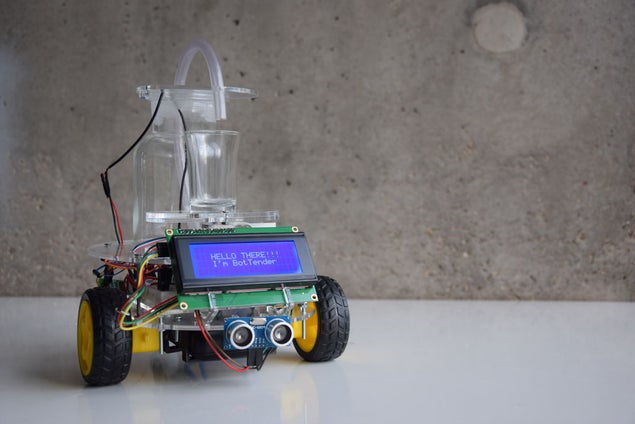
BotTender, a bartender assistant that pours the perfect shot!
BotTender is an autonomous robot that is designed with the aim of automatising bars. It is placed on top of the bar and detects the shot glasses in front of it. Once the glasses are detected, it approaches to the glass and asks for the customers to place their glasses on the robot. Then the perfect shot is waiting to be taken! When pouring is done, BotTender continues navigating along the bar until it detects the next customer with a glass.
The project conducted as part of the Computational Design and Digital Fabrication seminar in the ITECH masters program.
Step 1: List of Parts
ELECTRICAL COMPONENTS
1. Navigation:
2. Measuring Weight:
- (5KG) Straight bar type micro load cell (can be found in a kitchen scale)
- HX711 Load Cell Amplifier
3. Displaying:
- LCD Screen (4×20)
- LCD2004 I2C interface
4. Pouring:
- Mini Submersible Water Pump (DC motor 3-6V)
- 2n2222 Transistor (EBC)
- 1K Resistor
- 1N4007 Diode Rectifier
5. Other:
- Arduino UNO R3 Controller Board
- Mini Breadboard
- Battery Pack
- Jumper Wires (M/M, F/F, F/M)
- Soldering Iron
DESIGN
6. Off-the-shelf:
- (2) Wheels + Universal Wheel
- Glass Jar (8cm diameter)
- Shot Glass (3.5cm diameter)
- 9mm Water Tube
- (30) M3x16 bolts
- (15) M3x16 nuts
- (4) M3x50 bolts
- (5) M3x5 bolts
- (2) M5x16 bolts
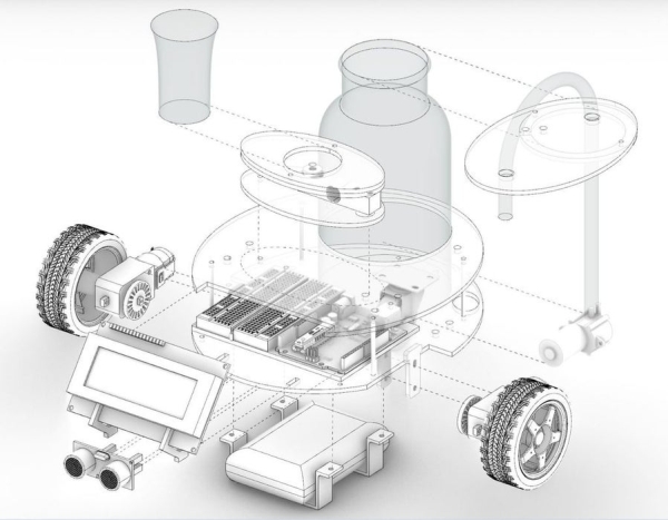
7. Custom parts:
- Laser cut on Plexiglass 3.0mm (25cm x 50cm): robot chassis top and bottom platforms, Arduino and breadboard platform, LDC holder, ultrasonic sensor holder, scale top and bottom platforms, Jar cap.
- 3D printed parts: Power bank holder
AND…
A LOT OF ALCOHOL!!!
Step 2: Logic and Setup
1. Navigation:
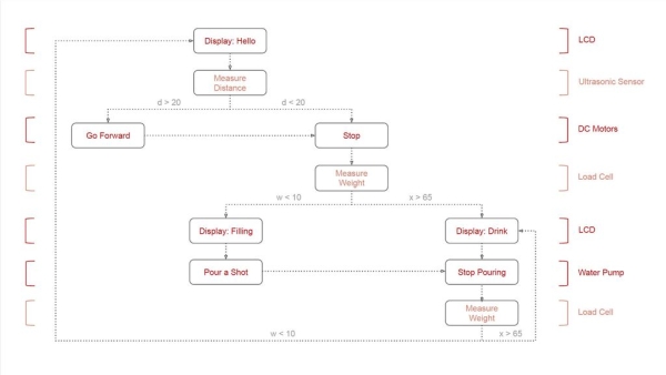
Navigation of the BotTender is controlled by the data taken from the ultrasonic sensor that is placed in front of the robot. As soon as the robot is plugged into the power source, the robot starts reading the distance to the shot glass and starts approaching towards it. When it reaches to a certain distance, it stops and waits for the customer to put the glass on the load cell plate.
The communication between the DC motors and the Arduino is achieved by using L293D Motor Driver IC. This module helps us to control the speed and the rotation direction of two DC motors. While the speed can be controlled using the PWM (Pulse Width Modulation) technique, the direction is controlled by using an H-Bridge.
If the frequency of the pulses increase, the voltage applied to the motors also increase, resulting with the motors rotating the wheels faster.
More detailed information on using the H Bridge to control DC motors can be found here.
2. Measuring weight:
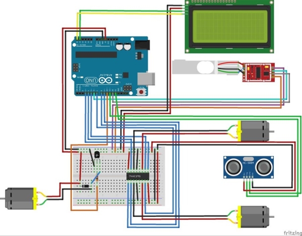
Logic and circuit: Use a Straight Bar Type Load Cell and an HX711ADC converter board to amplify the signal received form the weight sensor. Connect these to the Arduino and breadboard as indicated in the circuit diagram.
The HX711 is connected to:
- GND: Breadboard (-)
- DATA: pin 6 CLOCK: pin 2
- VCC: Breadboard (+)
- E+ : Connected to RED of the Load Cell
- E- : Connected to BLUE
- A- : Connected to WHITE
- A+ : Connected to BLACK
- B- : no connections
- B+ : no connections
The amplifier enables the Arduino to detect the changes in resistance from the Load cell. When pressure is applied, the electrical resistance will change in response to the applied pressure.
Setup: In our case, we are using a micro load cell (5KG). The load cell has 2 holes on the top and bottom and an arrow indicating the direction of deflection. With the arrow pointing down, attach the bottom of the scale to the robot’s top platform. Attach the opposite hole of the top of the load cell to the top piece of the scale.
Once connected to the Arduino, download the library for the HX711 amplifier at the bottom of this page and calibrate the load cell using the Calibration sketch provided below.
Download the HX711 library: https://github.com/bogde/HX711
Calibration sketch:
3. Displaying:
Logic and circuit: Connect the LCD Screen (4×20) to the I2C interface. If separated, soldering needs to be done. The I2C interphase consists of two signals: SCL and SDA. SCL is the clock signal, and SDA is the data signal. The I2C is connected to:
- GND: Breadboard (-)
- VCC: Breadboard (+)
- SDA: pin A4
- SCL: pin A5
Download the IC2 library: https://github.com/bogde/HX711
4. Pouring:
You’ll need a transistor, a 1K resistor and a Diode to connect the water pump to the Arduino. (Refer to the circuit diagram below). The water pump is activated when the load cell reads the weight of an empty glass. Once the glass is full, the load cell reads the weight and turns off the water pump.
Step 3: Circuit Diagram
Source: BotTender