Summary of Automatic Pet Feeder using Arduino
Summary: An Arduino-based Automatic Pet Feeder uses a DS3231 RTC module for accurate scheduling, a 16x2 LCD to display time and date, a 4x4 keypad and pushbutton to set feeding times, and a servo motor to rotate a 3D-printed container gate to dispense food. The system compares RTC time with the set time and actuates the servo briefly to release food.
Parts used in the Arduino-based Automatic Pet Feeder:
- Arduino UNO
- DS3231 RTC Module
- 16x2 LCD
- 4x4 Matrix Keypad
- Servo Motor
- Push Button
- Resistors
- Connecting Wires
- Breadboard
- 3D-printed pet feeder model (PLA, 4 parts)
Today we are constructing an Arduino-based Automatic Pet Feeder that can dispense food to your pet at scheduled times. It includes a DS3231 RTC Module to establish the feeding schedule for your pet with accurate time and date settings. Therefore, the device will automatically dispense or refill the food bowl at the set time based on your pet’s feeding schedule.
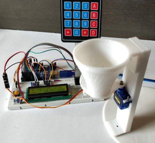
In this circuit, we are using a 16*2 LCD to display the time using DS3231 RTC Module with Arduino UNO. Also, a servo motor is used to rotate the containers to provide the food and 4*4 matrix keypad to manually set up the time for feeding the Pet. You can set the rotation angle and container opening duration according to the quantity of food you want to serve to your pet. The quantity of food may also depend upon your pet whether it’s a dog, cat or bird.
Material Required
- Arduino UNO
- 4*4 Matrix Keypad
- 16*2 LCD
- Push Button
- Servo Motor
- Resistor
- Connecting Wires
- Breadboard
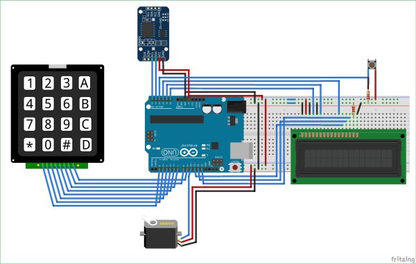
Circuit Diagram
In this Cat Feeder based on Arduino, we utilized an RTC (Real Time Clock) Module to obtain Time and Date. We utilized the 4*4 Matrix Keypad to manually input the Pet’s feeding schedule using a 16×2 LCD display. The Servo motor turns the container and releases the food at the designated time chosen by the user. The Date and Time are displayed using the LCD. The full solution can be seen in the video provided at the conclusion.
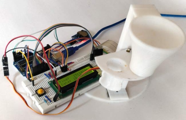
3D-Printed Pet Feeder Model
We have designed this Arduino Pet Feeder container using the 3D-printer. You can also print the same design by downloading the files from here. The material used for printing this model is PLA. It has four Parts as shown in the image below:
Assemble the four parts and connect the Servo Motor as shown in the picture below:
If you are new to 3D printing here is the starting guide. You can download the STL files for this pet feeder using arduino here.
DS3231 RTC Module
DS3231 is a RTC (Real Time Clock) module. It is used to maintain the date and time for most of the Electronics projects. This module has its own coin cell power supply using which it maintains the date and time even when the main power is removed or the MCU has gone through a hard reset. So once we set the date and time in this module it will keep track of it always. In our circuit, we are using DS3231 to feed the pet according to the time, set up by the Pet’s owner, like an alarm. As, clock reaches to the set time, it operates the servo motor to open the container gate and the food drops in the Pet’s food bowl.
Note: When using this module for the first time you have to set the date and time. You can also use RTC IC DS1307 for reading the time with Arduino.
Code and Explanation
Automatics Pet Feeder’s Complete Arduino Code is given at the end.
Arduino have default libraries for using the Servo motor and LCD 16*2 with it. But for using DS3231 RTC Module and 4*4 Matrix Keypad with the Arduino, you have to download and install the libraries. The download link for both the libraries is given below:
In the below code, we are defining libraries, “#include <DS3231.h>” for RTC module, “#include <Servo.h>” for Servo Motor, “#include <LiquidCrystal.h>” for 16*2 LCD, and “#include <Keypad.h>” for 4*4 Matrix Keypad.
#include <DS3231.h>
#include <Servo.h>
#include <LiquidCrystal.h>
#include <Keypad.h>
In the below code, we are defining the keymap for the 4*4 matrix keypad and assigning the Arduino pins for the Row and Columns of keypad.
char keys[ROWS][COLS] = {
  {'1','2','3','A'},
  {'4','5','6','B'},
  {'7','8','9','C'},
  {'*','0','#','D'}
};
byte rowPins[ROWS] = { 2, 3, 4, 5 };
byte colPins[COLS] = { 6, 7, 8, 9 };
Here, we are creating the keypad by using the command below in the code.
Keypad kpd = Keypad( makeKeymap(keys), rowPins, colPins, ROWS, COLS );
Assigning A4 and A5 Arduino pins to connect with SCL and SDA pins of DS3231. Also, assigning pins to the LCD and initializing the Servo motor.
DS3231  rtc(A4, A5);
Servo servo_test;      //initialize a servo object for the connected servo
LiquidCrystal lcd(A0, A1, A2, 11, 12, 13); // Creates an LC object. Parameters: (rs, enable, d4, d5, d6, d7)
In the below code, we are declaring the t1 to t6, key, and array r[6], and the feed.
int t1, t2, t3, t4, t5, t6;
boolean feed = true;
 char key;
 int r[6];
In the code below, we are configuring all the elements at the beginning. Just as shown in the code snippet “servo_test.attach(10);”, a Servo motor is connected to the 10th pin of the Arduino. Setting A0, A1, and A2 as the Output Pin and starting up the LCD and RTC module.
void setup()
 {
  servo_test.attach(10);   // attach the signal pin of servo to pin9 of arduino
  rtc.begin();
  lcd.begin(16,2);
  servo_test.write(55);
  Serial.begin(9600);
  pinMode(A0, OUTPUT);
  pinMode(A1, OUTPUT);
  pinMode(A2, OUTPUT);
 }
Understanding how the loop operates is crucial. When the Pushbutton is pressed, it becomes high, represented as 1, and can be interpreted as “buttonPress = digitalRead(A3)”. It now enters the ‘if’ statement and invokes the ‘setFeedingTime’ function. Next, it evaluates the actual time with the time provided by the user. If the real time matches the entered time, then the Servo motor will rotate to an angle of 100 degrees and return to its original position after a 0.4-second delay.
void loop() {
lcd.setCursor(0,0);
int buttonPress;
buttonPress = digitalRead(A3);

if (buttonPress==1)
 setFeedingTime();
 lcd.print("Time:  ");
 String t = "";

 t = rtc.getTimeStr();
 t1 = t.charAt(0)-48;
 t2 = t.charAt(1)-48;
 t3 = t.charAt(3)-48;
 t4 = t.charAt(4)-48;
 t5 = t.charAt(6)-48;
 t6 = t.charAt(7)-48;

 lcd.print(rtc.getTimeStr());
 lcd.setCursor(0,1);
 lcd.print("Date: ");
 lcd.print(rtc.getDateStr());

 if (t1==r[0] && t2==r[1] && t3==r[2] && t4==r[3]&& t5<1 && t6<3 && feed==true)
 {
  servo_test.write(100);                   //command to rotate the servo to the specified angle
   delay(400);
  servo_test.write(55);
  feed=false;
 }
 }
In the void setFeedingTime() function code, After pressing the pushbutton we are able to enter the pet feeding time, then we have to Press ‘D’ to save that time. When the saved time matches with real time then servo start rotating.
void setFeedingTime()
{
  feed = true;
   int i=0;

  lcd.clear();
  lcd.setCursor(0,0);
  lcd.print("Set feeding Time");
  lcd.clear();
  lcd.print("HH:MM");
  lcd.setCursor(0,1);
  while(1){
    key = kpd.getKey();
    char j;

  if(key!=NO_KEY){
    lcd.setCursor(j,1);
    lcd.print(key);
    r[i] = key-48;
    i++;
    j++;

    if (j==2)
    {
      lcd.print(":"); j++;
    }
    delay(500);
  }

  if (key == 'D')
  {key=0; break; }
  }
}
Working of the Automatic Pet Feeder
Once the code is uploaded to the Arduino Uno, the 16*2 LCD will show the current time and date. When the pushbutton is activated, it prompts for the Pet’s feeding time and requires inputting the time through the 4*4 matrix Keypad. The screen will indicate the time that was inputted and when you press ‘D’, it will store the time. If the current time matches the set time, the servo motor moves from 55⁰ to 100⁰ and then returns to its original position after a delay. Thus, the Servo motor is linked to the Food Container gate, causing it to open as it rotates, allowing for food to drop into the bowl or plate. 0.4 seconds later, the Servo motor rotates once more and shuts the gate. The entire procedure finishes in just a few seconds. This is how your pet will receive the food at the designated time automatically.
Adjust the time and temperature based on the type of food.
Code
#include <DS3231.h>
#include <Servo.h>
#include <LiquidCrystal.h>
#include <Keypad.h>
const byte ROWS = 4; // Four rows
const byte COLS = 4; // Three columns
// Define the Keymap
char keys[ROWS][COLS] = {
{‘1′,’2′,’3′,’A’},
{‘4′,’5′,’6′,’B’},
{‘7′,’8′,’9′,’C’},
{‘*’,’0′,’#’,’D’}
};
// Connect keypad ROW0, ROW1, ROW2 and ROW3 to these Arduino pins.
byte rowPins[ROWS] = { 2, 3, 4, 5 };
// Connect keypad COL0, COL1 and COL2 to these Arduino pins.
byte colPins[COLS] = { 6, 7, 8, 9 };
// Create the Keypad
Keypad kpd = Keypad( makeKeymap(keys), rowPins, colPins, ROWS, COLS );
DS3231 rtc(A4, A5);
Servo servo_test; //initialize a servo object for the connected servo
LiquidCrystal lcd(A0, A1, A2, 11, 12, 13); // Creates an LC object. Parameters: (rs, enable, d4, d5, d6, d7)
//int angle = 0;
// int potentio = A0; // initialize the A0analog pin for potentiometer
int t1, t2, t3, t4, t5, t6;
boolean feed = true; // condition for alarm
char key;
int r[6];
void setup()
{
servo_test.attach(10); // attach the signal pin of servo to pin9 of arduino
rtc.begin();
lcd.begin(16,2);
servo_test.write(55);
Serial.begin(9600);
pinMode(A0, OUTPUT);
pinMode(A1, OUTPUT);
pinMode(A2, OUTPUT);
}
void loop()
{
lcd.setCursor(0,0);
int buttonPress;
buttonPress = digitalRead(A3);
if (buttonPress==1)
setFeedingTime();
//Serial.println(buttonPress);
lcd.print(“Time: “);
String t = “”;
t = rtc.getTimeStr();
t1 = t.charAt(0)-48;
t2 = t.charAt(1)-48;
t3 = t.charAt(3)-48;
t4 = t.charAt(4)-48;
t5 = t.charAt(6)-48;
t6 = t.charAt(7)-48;
lcd.print(rtc.getTimeStr());
lcd.setCursor(0,1);
lcd.print(“Date: “);
lcd.print(rtc.getDateStr());
if (t1==r[0] && t2==r[1] && t3==r[2] && t4==r[3]&& t5<1 && t6<3 && feed==true)
{
servo_test.write(100); //command to rotate the servo to the specified angle
delay(400);
servo_test.write(55);
feed=false;
}
}
void setFeedingTime()
{
feed = true;
int i=0;
lcd.clear();
lcd.setCursor(0,0);
lcd.print(“Set feeding Time”);
lcd.clear();
lcd.print(“HH:MM”);
lcd.setCursor(0,1);
while(1){
key = kpd.getKey();
char j;
if(key!=NO_KEY){
lcd.setCursor(j,1);
lcd.print(key);
r[i] = key-48;
i++;
j++;
if (j==2)
{
lcd.print(“:”); j++;
}
delay(500);
}
if (key == ‘D’)
{key=0; break; }
}
}
Video
Source: Automatic Pet Feeder using Arduino
- How does the feeder keep accurate time?
It uses the DS3231 RTC module which maintains date and time with its coin cell backup. - How do you set feeding times?
Press the pushbutton, enter HH:MM via the 4x4 matrix keypad, and press D to save. - What triggers the servo to dispense food?
The Arduino compares the RTC time with the saved time and moves the servo when they match. - Which pins connect the DS3231 to Arduino?
The DS3231 is connected to Arduino A4 (SDA) and A5 (SCL) as shown in the code. - Which pin is the servo connected to?
The servo signal pin is attached to digital pin 10 in the provided code. - How is the time displayed to the user?
The 16x2 LCD displays the current time and date from the RTC module. - Can the feeder be physically made with 3D printing?
Yes, a 3D-printed PLA model in four parts is used for the container and can be downloaded and printed. - What libraries are required for this project?
The code uses DS3231, Servo, LiquidCrystal, and Keypad libraries. - How long does the servo hold the gate open?
The servo moves to 100 degrees, delays 400 ms, then returns to 55 degrees.