Summary of Automatic Irrigation System (Arduino) With Usb Type DC Submersible Water Pump
This project uses an Arduino UNO to automate irrigation: a soil moisture sensor triggers a 5V USB submersible pump when moisture crosses set thresholds, while an ultrasonic sensor monitors tank water level and a buzzer warns when low. Separate power supplies and USB interfacing plus a 5V regulator PCB protect the pump and sensors. Schematics for regulator and USB interface (with TIP120) and wiring, programming in Arduino IDE, and enclosure details are provided. System tested successfully and runs on rechargeable battery power for mobility and safety.
Parts used in the Automatic Irrigation System (Arduino):
- Arduino UNO x 1
- 5V soil moisture sensor with digital and analog output x 1
- 5V Ultrasonic sensor (HC-SR04) x 1
- 5V USB type submersible water pump x 1
- 5V buzzer x 1
- Bunch of rainbow wire with connectors (male-male, male-female)
- 9V battery x 1
- 1.2V NiMh AA rechargeable battery x 8 (8 x 1.2V = 9.6V)
- 5000mAh portable battery charger x 1
- 280mm x 280mm x 130mm weatherproof enclosure x 1
- 5V voltage regulator circuit PCB (components: 7805, 330nF cap, 110nF cap, 5mm LED, 470 Ohm resistor, 2-port power connectors)
- USB interfacing circuit PCB (components: TIP120 transistor, 10k resistor, 1N4007 diode, 5mm LED, 90 degree USB Type A, 90 degree USB Type B, 2-port power connector)
This mini project is involved to use Arduino to control submersible watre pump when soil reach below or above predefined moisture level.
How it works ❓
1. Soil moisture sensor is reading analog signal which transmit to Arduino.
2. Arduino control submersible water pump ON or OFF. Water pump operates when moisture level reach predefined value. Also, the water pump shall be stopped when reach predefined value.
3. Ultrasonic sensor is used to monitor predefined value of low water level. Warning sound is provided by buzzer when low water level detected. User is required to refill water to water tank manually.
4. The submersible water pump cannot be operated when low water level even if moisture level reach below or above predefined moisture value.
Step 1: Hardware/PCB List
Hardware
-> Arduino UNO x 1 no.
-> 5V soil moisture sensor c/w digital and analog output x 1 no.
-> 5V Ultrasonic sensor (HC-SR04) x 1 no.
-> 5V USB type submersible water pump x 1 no.
-> 5V buzzer x 1 no.
-> bunch of rainbow wire with connector (male – male, male – female)
-> 9V battery x 1 no.
-> 1.2V NiMh AA rechargeable battery x 8 nos. (8 x 1.2V = 9.6V)
-> 5000mAh portable battery charger x 1 no.
-> 280mm (L) x 280mm (W) x 130mm (H) weatherproof type enclosure x 1 no.
PCB
-> 5V voltage regulator circuit x 1 no.
-> USB interfacing circuit x 1 no.
Step 2: Functions of Hardware/PCB
1-> Arduino UNO
It used to keep reading analog signal from soil moisture sensor. In addition, It controls submersible water pump ON/OFF when reach predefined moisture level. Also, it monitors low water level.
2-> 5V soil moisture sensor
This sensor can provide digital signal or analog signal to Arduino.
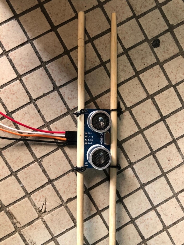
3-> 5V Ultrasonic sensor
This sensor keep monitoring water level. Signal shall be sent to Arduino when reach predefined value.
4-> 5V USB type submersible water pump
It is controlled by Arduino which can turn ON/OFF submersible water pump automatically.
5-> 5V buzzer x 1 no.
Sound to warn low water level occur.
6-> Bunch of rainbow wire with connector
Interfacing necessary component and circuits
7-> 9V battery
Independent power supply for 5V regulator.
8-> 1.2V NiMh AA rechargeable battery
Independent power supply for Arduino.
9-> 5000mAh portable battery charger
Independent power supply for 5V submersible water pump.
10-> Weatherproof type enclosure
For arrangement all necessary component and provide weatherproof feature.
11-> 5V voltage regulator circuit (PCB)
Power supply of soil moisture sensor is provided by this voltage regulator.
12-> USB interfacing circuit (PCB)
Provide interfacing to 5000mAh portable battery charger, 5V submersible water pump and signal from Arduino.
Step 3: Automatic Irrigation System Control Logic
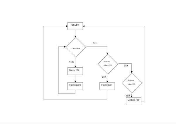
Initially, Arduino analyzes data from ultrasonic sensor to check if water level is over 20cm. An alarm will sound if the water level in the tank drops too low. The programming has caused the submersible water pump to be unusable.
Furthermore, Arduino checks whether the moisture level is at or above 700 when the water level decreases below 20cm. In this scenario, Arduino will transmit a signal to the USB interface circuit to turn on the submersible water pump. If not, it confirms that the humidity valve is under 500. The USB interface circuit receives a signal from the Arduino in order to turn off the water pump.
According to the supplier’s recommendation, the water pump will stop working or get damaged if it operates without water. As a result, a water level sensor is installed to stop the pump from functioning if the moisture level exceeds or falls below the specified limit.
Step 4: Schematic Diagram of 5V Voltage Regulator Circuit
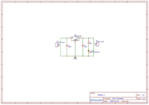
This 5V voltage regulator circuit is power from 9V battery and output 5V for soil moisture sensor. Necessary component show as below
-> 7805 x 1 no.
-> 2 ports power connector x 2 nos. (1 for INPUT & 1 for OUTPUT)
-> 330nF ceramic capacitor x 1 no.
-> 110nF ceramic capacitor x 1 no.
-> 5mm LED x 1 no. (visual inform user output is available)
-> 470 Ohm resistor x 1 no.
The schematic drawn by EasyEDA. In addition, this program can generate PCB base on schematic. It provides autoroute feature for you. However, you can route the track manually too.
Step 5: Schematic Diagram for USB Interfacing Circuit
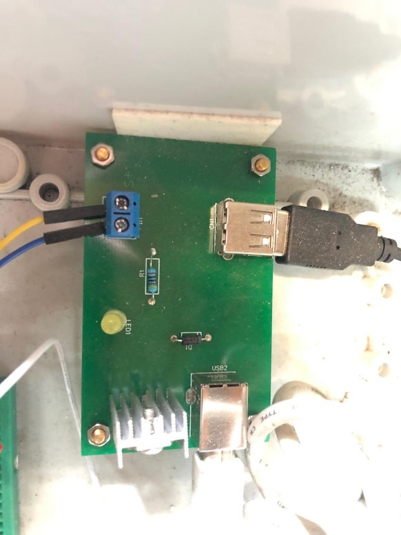
This USB interfacing circuit is used for provide connection for USB and 2 ports power connectors. Necessary component show as below
-> TIP120 transistor x 1 no.
-> 2 ports power connector x 1 no.
-> 10k resistor x 1 no.
-> 5mm LED x 1 no. (visual inform user signal is ON or OFF status)
-> 1N4007 diode x 1 no.
-> 90 degree USB type A x 1 no.
-> 90 degree USB type B x 1 no.
The 5000mAh power bank is connected to USB Type B, while the 5V DC water pump is connected to USB Type A. To monitor the signal from the Arduino, attach the power connector of the two ports to an Arduino PIN. Arduino generates a HIGH signal when it senses dry soil. On the other hand, a LOW signal will be generated once moisture reaches a specific level. The transistor is designed to act as a switch for controlling the circuit’s on and off state. The water pump is activated by a HIGH signal but deactivated by a LOW signal from the Arduino.
Just like I mentioned in the previous schematic, this drawing was also created using EasyEDA.
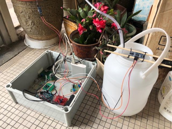
Step 6: Wiring Diagram
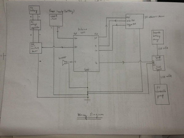
This diagram demonstrates the wiring of the automatic irrigation system. Separate power supplies are required because the Arduino’s 5V output cannot support both the ultrasonic sensor and soil moisture sensor at the same time. Nevertheless, the water pump also operates on its own separate power supply. The nameplate of the water pump shows a power consumption of 1.5W is required.
P=I x V
1.5W = I x 5V
I = 0.3A or 300mA
According to Arduino specification, maximum dc current per I/O pin is 40mA. Hence, it is good to use external power supply rather than Arduino 5V output for supplying voltage to equipment such as fan, water pump and so on.
Step 7: Programming and Upload to Arduino

The coding is carried out using Arduino IDE software version 1.8.13. You can choose to get this IDE directly from the Arduino website. Programming for the Arduino board is done in the C language. Once completed, the program can be compiled. Please be informed that the program will not be able to be uploaded if any errors are found during compliance checks. Once you have pinpointed the errors, you are able to upload the program to Arduino.
Step 8: Conclusion

The system operates properly during testing and commissioning. I am satisfied with the result since it operated as intended. However, I was pondering over whether to utilize AC or DC as the power supply. I ultimately chose a DC power supply since my AC outlets are mostly occupied by other electronic devices. Yet, I prefer to keep the AC socket away from any water source. Hence, the system makes use of a rechargeable battery. Moreover, the system enhances its mobility by using battery-powered resources.
Feel free to leave a comment if you have any questions or ideas.
I appreciate your gratitude
Source: Automatic Irrigation System (Arduino) With Usb Type DC Submersible Water Pump
- How does the system decide when to turn the water pump on or off?
The Arduino reads the soil moisture sensor and turns the pump on or off when moisture reaches predefined threshold values. - Can the pump operate if the tank water level is low?
No. The ultrasonic sensor detects low tank level and the Arduino disables the pump to prevent operation when water is low. - What triggers the low water level warning?
The ultrasonic sensor monitors tank level and when it drops below 20 cm the Arduino sounds the buzzer as a warning. - How is the water pump powered?
The 5V USB submersible pump is powered from a separate 5000mAh portable battery charger connected via the USB interfacing circuit. - Why are separate power supplies used in the system?
Because the Arduino 5V output cannot support all sensors and the pump; the pump and other components use independent power supplies to meet current requirements. - What components protect the pump from running dry?
The ultrasonic water level sensor and Arduino logic prevent the pump from running when tank level is below the safe threshold. - Which transistor is used to switch the pump in the USB interface circuit?
The TIP120 transistor is used as a switch to control the pump via signals from the Arduino. - What software is used to program the Arduino?
The Arduino IDE version 1.8.13 is used to write, compile, and upload the C language program to the Arduino board.