Summary of Arduino Solar Tracker Using LDR Sensor & Servo Motor
This project demonstrates an Arduino-based single-axis solar tracker designed to maximize energy efficiency by following the sun's movement. Using an Arduino Nano, two LDR sensors detect light intensity differences, while a servo motor adjusts the panel's angle accordingly. The system features a self-calibration mechanism via a momentary switch, eliminating the need for preset resistors. By aligning the panel with sunlight, this setup can increase power generation efficiency by approximately 25%.
Parts used in the Arduino Solar Tracker:
- Arduino Nano
- USB Cable
- SPDT Switch
- Momentary Switch
- 10K Ohm Resistors
- LDR Sensor
- Servo Motor 9g
- Power Source (9 or 12 Volt)
- PCB (Copper Clad/Zero PCB)
Arduino Solar Tracker
Solar energy is one of the fastest growing industries in the world; today more than 65 GW energy is produced by solar power. Since solar energy is renewable, it is a good power source, especially for developing countries.
In this project, I am going to show you how to make a solar tracker using Arduino Nano. The solar panel tracker is designed to follow the sun movement so that maximum light intensity hits on the solar panel, thus increasing the power efficiency. Use of a solar tracker circuit in the field of energy production will increase its efficiency by almost 25%. This system can also be successfully implemented in other solar energy based projects water heaters and steam turbines.
There are basically two types of Arduino sun trackers. One of them is the single axis solar tracker and the other is dual axis. Single axis solar tracking system moves the solar panel from east to west in a day to point in the direction of the sun. Dual axis solar trackers uses the motor to move the solar panel in all four directions (North-South & East-West).
South to north is not a viable or big movement, because this movement covers only 20 degrees in half year and in remaining half year it moves from north to south and we can set this, manually in a week. Since the East-West tracking is more important, I will be explaining more of the single axis solar tracking.
![]()
Arduino Solar Tracker – Working
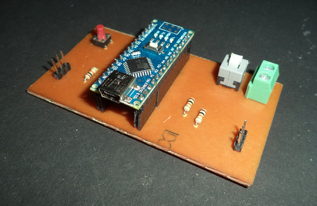
In this project an Arduino Nano is used, which works as a controlling unit. Two LDR’s (Light Dependent Resistor) are also connected to analog pins of the Arduino. A dummy solar plate is attached in parallel to the axis of servo motor and both the sensors are kept on the dummy solar plate as shown in the figure below.
The arrangement is made in such a way that the movement of sun is from sensor 1 to sensor 2, as shown in the mage below.
![]()
The arrangement is made in such a way that the movement of sun is from sensor 1 to sensor 2, as shown in the mage below.
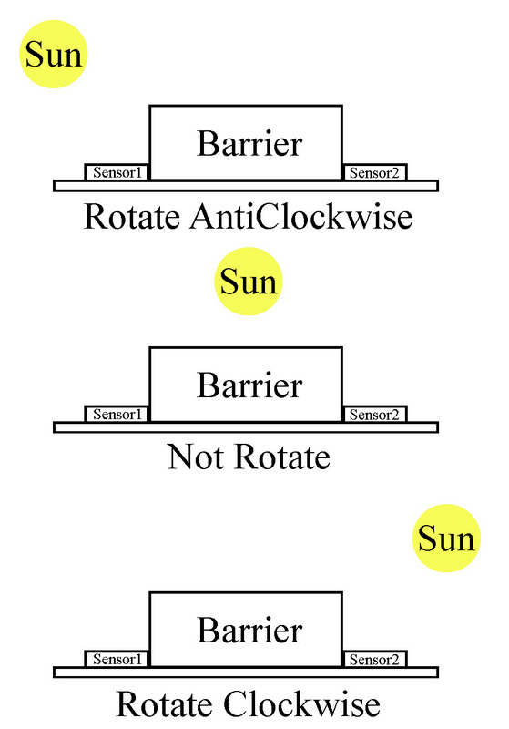
There are three conditions to be followed:-
Condition 1:
Sun is in left side – Light on sensor1 is high because shadow of barrier falls on sensor 2 so solar plate moves clockwise.
Condition 2:
Sun is in right Side – Light on sensor2 is high because shadow of barrier falls on sensor1 so solar plate movie anticlockwise.
Condition 3:
Sun is in the middle – Light on both sensors are equal so, plate will not rotate in any direction.
Output is shown in the demo video below. You can see that the plate moves in the direction of light, but some fluctuation is visible in video because light is coming from multiple sources. Fluctuation is automatically removed when system is placed in direct sunlight.
Components Used
Circuit
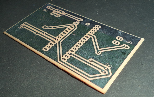
A PCB (Printed circuit board) is designed for this Solar Tracker Arduino. Using a breadboard or Zero PCB are also other simpler options to create this solar tracker circuit. For PCB printing refer the PCB design shown below.
![]()
PCB Design for Arduino Solar Tracker
The circuit diagram shown below. This is useful for ZERO PCB or breadboard circuit.
In the circuit two LDR (Light Dependent Resistors) sensors are used to sense the light. Since LDR is an analogue sensor they are connected to the analog pins A0 and A1 of Arduino. The sensors are connected in series with 10 k ohm resistors.
A servomotor is also connected to the digital pin D10. D10 is a PWM (pulse width modulation) pin. A momentary switch is also connected to digital pin D2, mainly for calibration purposes. When the switch is pressed D2 pin will act as the ground (GND). A 12-volt adapter or 9 volt battery, can be used to power this whole circuit. RAW pin in Arduino Nano is the power pin.
Program/Code
We are using EEPROM and Servo Motor so two header files “EEPROM.h” and “Servo.h” are used in the starting of code. Next a servo motor is defined by the name “myservo”. Two integers are defined by names sensor1 and sensor2. Calibration switch is connected to D2 pin so another integer is defined by “calswitch”. Other integers are defined by names val1, val2, pos, & error. All these states are used for internal processes.
In the void setup sensor1, sensor2 and calswitch are defined as input. Now servo is activated by “myservo.attach(10)” function.
In the void loop section first of all an “if” condition is used for calibration. When momentary switch is pressed this “if” condition becomes true. In this condition servo the motor is deactivated by function “myservo.detach(10)”. Next values of sensors are assigned in integer “val1” and “val2”. According to the value of val1, val2 & error, thestate is saved in EEPROM using function “EEPROM.write()”, and a delay of 1 second is used at the end of this loop. Now calibration process is done.
![]()
In else loop “myservo.attach” is used to activate the servo, val1 and val2 are read by using “analogRead” function, after that state and error is read from EEPROM using “EEPROM.read” function after that error is removed from val1 or val2.
Three conditions are described in working of project, these conditions are executed in the code using “if else” conditions, in this way servo rotates clockwise or anticlockwise according to sunlight.
The rotational movement of the solar panel should not should be confined between o and 90 degrees. When “pos” becomes more then 90 degree an if condition is used for making this 90 degree and same concept is used when it becomes less than 0 degree.
Calibration
This project is featured by self-calibration so it does not need any preset or variable resistor for calibration; you just need to press a momentary switch. For calibration, press and hold the switch, which is connected to pin D2 and rotate the solar plate in direction of sun and release after 2- 3 seconds. By using this simple process, Arduino reads the value of sensors and saves the error state in EEPROM. This system needs one time calibration.
Source : Arduino Solar Tracker Using LDR Sensor & Servo Motor
- How does the solar tracker increase efficiency?
The system increases power efficiency by almost 25% by ensuring maximum light intensity hits the solar panel. - What type of solar tracking is explained in detail?
The article explains the single axis solar tracking system which moves the panel from east to west. - Can I use a breadboard instead of a PCB?
Yes, using a breadboard or Zero PCB are simpler options to create this circuit besides a designed PCB. - Does the system require manual calibration variables?
No, the project features self-calibration and does not need any preset or variable resistor. - How do I calibrate the solar tracker?
Press and hold the momentary switch connected to pin D2 while rotating the plate toward the sun, then release after 2-3 seconds. - Which pins are used for the LDR sensors?
The two LDR sensors are connected to the analog pins A0 and A1 of the Arduino. - What happens when both sensors receive equal light?
When light on both sensors is equal, the plate will not rotate in any direction. - How is the servo motor controlled in the code?
The servo motor is activated using myservo.attach(10) and deactivated using myservo.detach(10).