Summary of Arduino Sketch WS2801LED
This article details an Arduino sketch for driving WS2801 RGB LED modules via SPI. It explains the protocol's 24-bit data requirement, daisy-chaining capabilities, and specific wiring configurations. The code demonstrates sending color data to three pixels in a loop with timing delays to ensure proper updates, noting that the color sequence may vary based on physical wiring (e.g., Blue-Red-Green).
Parts used in the WS2801 RGB LED SPI Module Project:
- Arduino UNO
- WS2801 RGB LED Modules
- SPI Library
- DAT Pin (MOSI)
- CLK Pin (SCK)
- GND (Ground)
This sketch is used by Exercise: WS2801 RGB LED SPI Module.
Full Source Code
The full code is all in one file WS2801LED.ino.
// -*- mode:c++; -*-
/// @file WS2801LED.ino
///
/// @brief Example for driving several WS2801 RGB LED modules over SPI on an Arduino UNO.
///
/// @author Garth Zeglin
/// @date 2014-09-13
///
/// @remarks The WS2801 LED driver has three current controlled LED outputs with
/// 8-bit precision (256 levels). It is controlled over SPI by sending 24 bits
/// of pixel data at up to 25MHz rate. Additional data is then relayed to the output
/// SPI pins to feed daisy-chained drivers. Once the bus is quiescent for 500
/// microseconds, the data is applied to the outputs and the chip is ready to
/// receive more values.
///
/// So a large number of of drivers can be fed on each channel, limited only by
/// the overall refresh rate. But the data must be fed without interruption to
/// avoid prematurely ending the cycle.
///
/// The actual color data sequence depends upon the wiring of the module; on one
/// particular strip light tested the actual sequence was blue-red-green.
///
/// Note that the relay scheme means that first three bytes output feed the
/// first module, the second three the second module, etc. In other words, the
/// strand is not a shift register. Extra data has no effect.
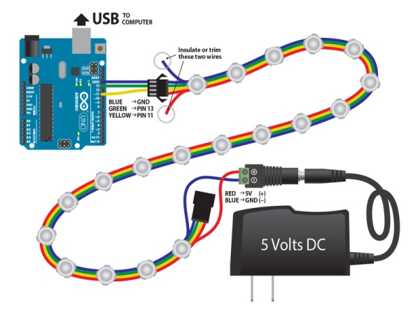
/// This sketch assumes the following electrical connections from the Arduino to
/// the first module in a chain:
/// PIN11 (MOSI) -> DAT
/// PIN13 (SCK) -> CLK
/// GND -> GND
// Include the SPI library.
#include <SPI.h>
void setup()
{
SPI.begin(); // initialize SPI hardware
}
void loop()
{
static int cycle = 0;
// on each iteration, shift out RGB data for several pixels, then delay to allow the device to update.
for (int pixel = 0; pixel < 3; pixel++ ) {
uint8_t red = 3 * (cycle + 32*pixel);
uint8_t green = 5 * (cycle + 32*pixel);
uint8_t blue = 7 * (cycle + 32*pixel);
SPI.transfer( blue );
SPI.transfer( red );
SPI.transfer( green );
}
delay(1); // delay 1 millisecond to allow outputs to update
cycle++; // update the overall animation
// add a delay to control the overall frame rate
delay(20);
}
Source: Arduino Sketch WS2801LED
- How is the WS2801 driver controlled?
It is controlled over SPI by sending 24 bits of pixel data at up to 25MHz rate. - Can multiple drivers be fed on each channel?
Yes, a large number of drivers can be fed on each channel limited only by the overall refresh rate. - What happens if data is interrupted during transmission?
Data must be fed without interruption to avoid prematurely ending the cycle. - Does the strand act as a shift register?
No, the relay scheme means the strand is not a shift register; extra data has no effect. - Which Arduino pins are connected to DAT and CLK?
PIN11 (MOSI) connects to DAT and PIN13 (SCK) connects to CLK. - How long must the bus be quiescent before data applies to outputs?
The bus must be quiescent for 500 microseconds before data is applied to the outputs. - What determines the actual color data sequence?
The actual color data sequence depends upon the wiring of the module. - How many bytes output feed the first module?
The first three bytes output feed the first module.