
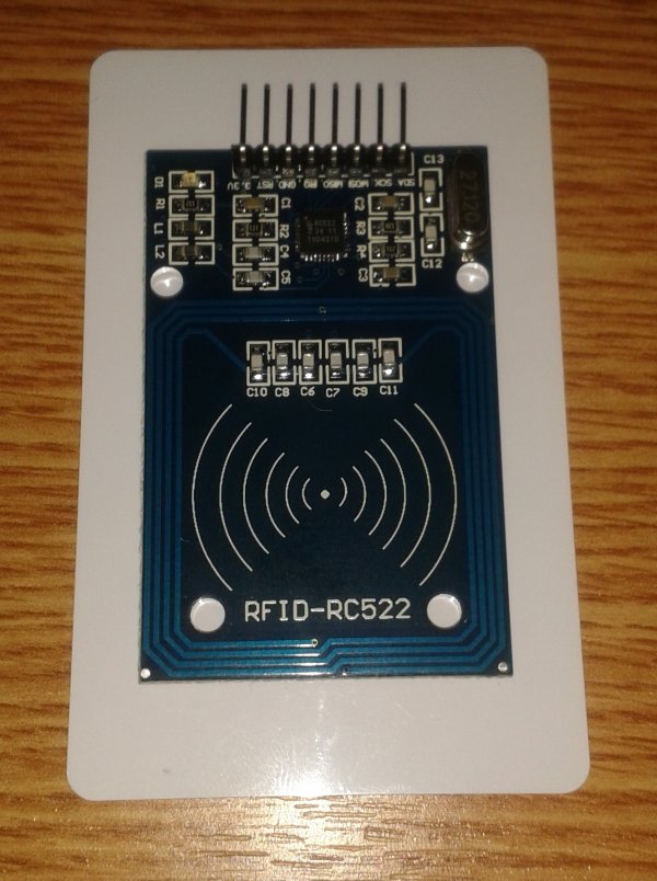
I just received my RC522 RFID reader and made this simple Arduino access control system that uses the reader, a buzzer for the alarm and a relay shield for the security system. The relay can be used to open a door lock and if you need a louder alarm then you can replace the small buzzer with a high power siren.
I will not talk about the RFID reader because you can find a lot of information about it on the web, but I will talk about the Arduino sketch which is very important. So, let’s start by watching this 7 minutes video to see the entire system in action:
/** source: http://www.electroschematics.com/11301/arduino-rfid-reader-rc522-access-control-system/
- * Read a card using a mfrc522 reader on your SPI interface
- * Pin layout should be as follows (on Arduino Uno):
- * MOSI: Pin 11 / ICSP-4
- * MISO: Pin 12 / ICSP-1
- * SCK: Pin 13 / ISCP-3
- * SS: Pin 10
- * RST: Pin 9
- */
-

- #include <SPI.h>
- #include <RFID.h>
- #define SS_PIN 10
- #define RST_PIN 9
- RFID rfid(SS_PIN,RST_PIN);
- int startAlarm = false;
- int resetAlarm = 2;
- int relay = 7;
- int alarm = 8;
- int serNum[5];
- int cards[][5] = {
- {209,128,106,69,126}, // card 1
- {101,220,213,229,137} // card 2
- };
- bool access = false;
- void setup(){
- Serial.begin(9600);
- SPI.begin();
- rfid.init();
- pinMode(resetAlarm, INPUT);
- pinMode(relay, OUTPUT);
- pinMode(alarm, OUTPUT);
- digitalWrite(relay, HIGH); // or LOW if you have a regular relay
- attachInterrupt(0, reset_alarm, LOW);
- }
- void loop(){
- if(rfid.isCard()){
- if(rfid.readCardSerial()){
- Serial.print(rfid.serNum[0]);
- Serial.print(“,”);
- Serial.print(rfid.serNum[1]);
- Serial.print(“,”);
- Serial.print(rfid.serNum[2]);
- Serial.print(“,”);
- Serial.print(rfid.serNum[3]);
- Serial.print(“,”);
- Serial.print(rfid.serNum[4]);
- Serial.println(“”);
- for(int x = 0; x < sizeof(cards); x++){
- for(int i = 0; i < sizeof(rfid.serNum); i++ ){
- if(rfid.serNum[i] != cards[x][i]) {
- access = false;
- break;
- } else {
- access = true;
- }
- }
- if(access) break;
- }
- }
- if(access){
- Serial.println(“Welcome!”);
- startAlarm = false;
- digitalWrite(relay, LOW); // HIGH with regular relay
- } else {
- Serial.println(“Not allowed!”);
- startAlarm = true;
- digitalWrite(relay, HIGH); // LOW with regular relay
- }
- }
- if(startAlarm) {
- digitalWrite(alarm, HIGH);
- } else {
- digitalWrite(alarm, LOW);
- }
- rfid.halt();
- }
- void reset_alarm(){
- startAlarm = false;
- }
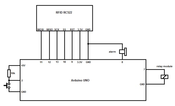 First off all extract the RFID library and move the folder inside the Libraries folder where you’ve installed Arduino software. Now connect the RC522 reader to the board as you can see on the first lines in the sketch:
- MOSI -> pin 11
- MISO -> pin 12
- SCK -> pin 13
- SS (or SDA) -> pin 10
- RST -> pin 9
- 3.3V -> 3.3V
- GND -> GND
The resetAlarm integer is the Arduino pin where we connect the button that is used the reset the alarm. The relay is connected to pin 7 and the active buzzer to pin 8.
On the next lines you need to change the cards codes with the ones you have. You’ll have to read the codes in the serial monitor then decide which ones you want to use to allow access in your room (watch the video to see how I’ve made it). You can use only one card or as many as you want, but add the comma after each array of elements.
The boolean access is set to false and is used to store the value true or false when we read the tags (or cards). If you go to line 63 you can see a for loop where we check to see if the values we stores in the cards array are the same as the ones we read from our RFID reader and if are the same then we set access variable to true.
Now, on line 76 if access is true we print “Welcome” in the console, set startAlarm to false so it doesn’t turn on, and activate the relay. If is false then we setAlarm to true and let the relay in its initial state.
On line 87 we check to see if the startAlarm is set to true and if so then we turn on the buzzer. If is false then do nothing.
We also have a resetAlarm button that is used to turn off the buzzer and the relay will not be activated. We might as well use a good RFID tag to stop it but now the relay will be activated.
This project is very simple and can be a good starting point to develop more complicated applications where you use the RC522 RFID reader. Stay tuned because I will try to make some new and interesting systems based on this reader.
For more detail: Arduino RFID Reader RC522 + Access Control System