Summary of Arduino RFID Lock Tutorial
This article guides users in building an Arduino-based RFID lock system using an RFID reader and an OLED display. The project reads a tag's Unique ID (UID) and compares it to a stored value; if they match, the display shows "Unlocked." It details component selection, wiring connections via SPI and I2C interfaces, necessary library installations, and code logic for authentication.
Parts used in the Arduino RFID Lock System:
- Arduino Uno
- RFID Reader
- OLED display
- Small breadboard
- Wires
- Powerbank (Optional)
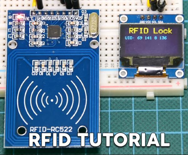
Dear friends welcome to another Instructable. This is Nick from educ8s.tv and today we are going to learn how to use this RFID Reader with Arduino in order to build a simple lock system.
For the first time, we are going to use RFID tags with Arduino. I have built a simple project which reads the Unique ID (UID) of each RFID tag we place close to the reader and displays it on this OLED display. If the UID of the tag is equal to a predefined value that is stored in Arduino’s memory, then in the display we are going to see the “Unlocked” message. If the Unique ID of the card is not equal to the predefined value, the Unlock message won’t appear. Cool isn’t it?
There is a lot to cover, so let’s get started!
Step 1: Get All the Parts
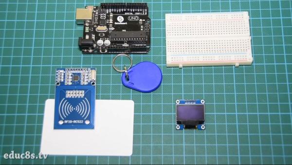
The parts needed in order to build this project are these:
- An Arduino Uno ▶ http://educ8s.tv/part/ArduinoUno
- An RFID Reader ▶ http://educ8s.tv/part/RFID
- OLED display ▶ http://educ8s.tv/part/OLED096
- A small breadboard ▶ http://educ8s.tv/part/SmallBreadboard
- Some wires ▶ http://educ8s.tv/part/Wires
Optional Parts:
- Powerbank ▶ http://educ8s.tv/part/Powerbank
The total cost of the project is around $15.
Step 2: The RC522 RFID Reader
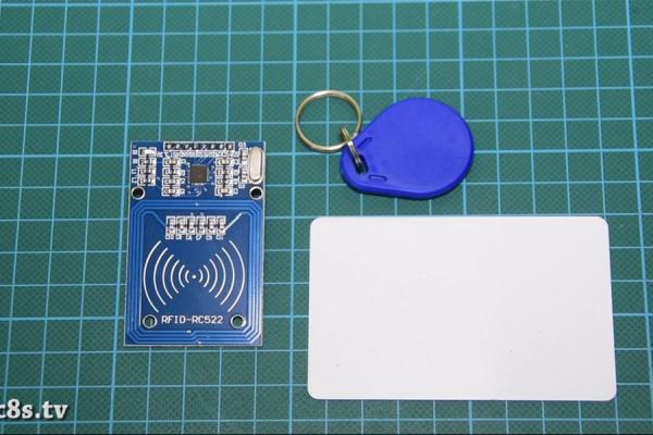
Each RFID tag has a small chip inside. If I place a flashlight under this RFID card you can see the small chip and the coil that surrounds it. This chip does not have a battery in order to get power. It receives power from the reader, this device, wirelessly using this big coil. The reader can read an RFID card like this one from a distance up to 20mm!
The same chip exists in keychain RFID tags as well.
Each RFID tag has a unique number that identifies it. That’s the UID that we display on the OLED display. Except from this UID, each tag can store data. In this type of cards we can store up to 1K of data! Impressive isn’t it? We won’t use this functionality today but will do so in a future Instructable. Today, all we are interested in is to identify a specific card by its UID. The cost of the RFID reader and these two RFID cards is around $4.
Step 3: OLED Display
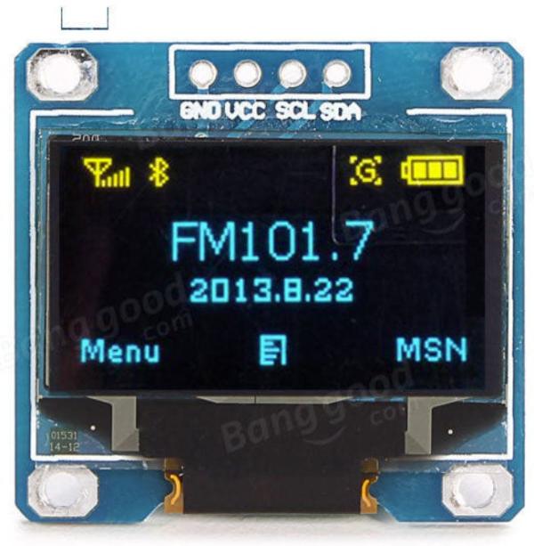
This is a very nice display to use with Arduino. It is an OLED display and that means that it has a low power consumption. The power consumption of this display is around 10-20 mA and it depends on how many pixels are lit.
The display has a resolution of 128×64 pixels and it is tiny in size. There are two variations of the display. One of them is monochrome, and the other one like the one I use can display two colors, yellow and blue. The upper part of the screen can only display yellow, the lower part only blue.
This OLED display is very bright, and it has a great library support. Adafruit has developed a very nice library for this display. In addition to that, the display uses the I2C interface, so the connection with Arduino is incredibly easy. You only need to connect two wires except for Vcc and GND. If you are new to Arduino and you want an inexpensive and easy to use display to use with your project, start with display. It is the easiest way to add a display to your Arduino project. I have prepared a detailed tutorial on how to use this display which I have attached to this Instructable.
Step 4: Connect All the Parts
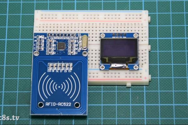
The connection with the Arduino Uno board is very simple. At first, let’s connect the power of both the reader and the display.
Be careful, the RFID reader must be connected to the 3.3V output of the Arduino Uno or it will be destroyed. Since the display can also work at 3.3V we connect the Vcc from both modules to the breadboards positive rail. This rail is then connected to the 3.3V output of the Arduino Uno. Next, we connect both GNDs to the breadboard GND rail. Then we connect the GND rail of the breadboard to Arduino GND.
OLED Display – Arduino
Vcc ▶ 3.3V
GND ▶ GND
SCL ▶ Analog Pin 5
SDA ▶ Analog Pin 4
RFID Reader – Arduino
RST ▶ Digital Pin 9
IRQ ▶ Unconnected
MISO ▶ Digital Pin 12
MOSI ▶ Digital Pin 11
SCK ▶ Digital Pin 13
SDA ▶ Digital Pin 10
The RFID reader module uses the SPI interface in order to communicate with Arduino. So we are going to use the hardware SPI pins of the Arduino UNO. RST pin goes to digital pin 9. IRQ pin stays unconnected. MISO pin goes to digital pin 12. MOSI pin goes to digital pin 11. SCK pin goes to digital pin 13 and lastly, SDA pin goes to digital pin 10. That’s it. The RFID reader is connected. We now have to connect the OLED display with Arduino using the I2C interface. So, the SCL pin of the display goes to Analog Pin 5 and SDA pin of the display to Analog Pin 4. If we now power up the project and place an RFID card close to the reader we can see that the project is working fine! Now it’s time to take a look at the code of the project.
Step 5: The Code of the Project
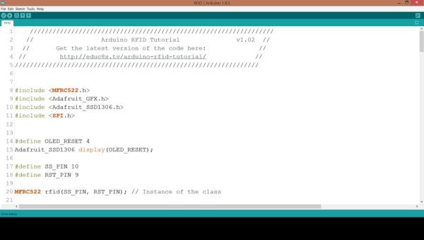
In order the project code to compile we need to include some libraries. First of all, we need the MFRC522 Rfid library. In order to install it, go to Sketch -> Include Libraries -> Manage libraries. Search for MFRC522 and install it. We also need the Adafruit SSD1306 library and the Adafruit GFX library for the display. Install both libraries with the same procedure. The Adafruit SSD1306 library needs a small modification. Go to the Arduino -> Libraries folder, open the Adafruit SSD1306 folder and edit the Adafruit_SSD1306.h library. Comment line 70 and uncomment line 69. Our display has a resolution of 128×64, that’s what we are defining here. Now we are ready to take a quick look at the code.
At first, we declare the value of the RFID tag that we want the Arduino to recognize. It is an array of integers.
int code[] = {69,141,8,136}; //This is the stored UID
Next, we initialize the RFID reader and the display.
rfid.PCD_Init();
display.begin(SSD1306_SWITCHCAPVCC, 0x3C);
After this, in the loop function, we check for a tag on the reader every 100 ms.
If there is a tag on the reader we read its UID and we print it on the display. Next, we compare the UID of the tag we just read, with the value that is stored in the code variable. If the values are the same, we display the UNLOCK message, else we don’t display this message.
if(match)
    {
      Serial.println("\nI know this card!");
      printUnlockMessage();
    }else
    {
      Serial.println("\nUnknown Card");
    }
Of course, you can modify this code in order to store more than 1 UID values in order the project to recognize more RFID tags.
This is just an example. As always you can find the code of the project attached to this Instructable.
Source: Arduino RFID Lock Tutorial
- How does the RFID reader power the tag?
The tag receives power wirelessly from the reader through a coil without needing its own battery. - Can the RFID reader read cards from a distance?
Yes, the reader can read an RFID card from a distance up to 20mm. - What voltage should the RFID reader be connected to?
The RFID reader must be connected to the 3.3V output of the Arduino Uno to avoid destruction. - Which interface does the OLED display use?
The OLED display uses the I2C interface for connection with the Arduino. - How do you modify the display resolution in the code?
You must edit the Adafruit_SSD1306.h file by commenting line 70 and uncommenting line 69. - What happens if the scanned UID matches the stored value?
The system prints Unknown Card to the serial monitor and displays the UNLOCK message on the screen. - Can the project recognize more than one RFID tag?
Yes, you can modify the code to store multiple UID values to recognize different tags.