
Summary of Arduino – motion triggered camera
This article details an Arduino-based motion tracker that triggers a Nikon D80 camera for timelapse photography using a PIR sensor. The system detects motion via infrared radiation differences and limits photo capture to two shots per trigger event to prevent continuous firing.
Parts used in the Arduino Motion Tracker:
- 220 Ohm resistor
- 10K Ohm resistor
- PIR sensor
- Infrared emitting diode
- LED
- Arduino Duemilanove with ATMEGA328
- Breadboard / Prototyping board
- Jumper/ Connector wires
- 9V power supply or USB power
- Soldering iron and solder
So having worked out that I can make a remote for my Nikon D80 to do some timelapse photography. I started thinking of things I can do to trigger the remote, below video shows it working but you’ll need sound to hear the shutter going.
First of all check out my tutorial for making the remote as this builds on that tutorial – also saves me having to recap and explain that. Arduino Nikon intervalometer infrared remote for timelapse photography.
Ok so now you know how I’m going to trigger the camera to take pictures. So now we need the sensor, for this I’m going to use a PIR (Pyroelectric InfraRed sensor) IC that works like a switch turning on when motion is detected, the one I’m using is basically a couple of IR emitters and sensors under a Fresnel lens – word of warning make sure you get the power supply right as they tend to smoke otherwise!. It works by measuring any difference to the background temperature and infrared radiation. I’ve also added an LED to signal when the PIR is on or off.
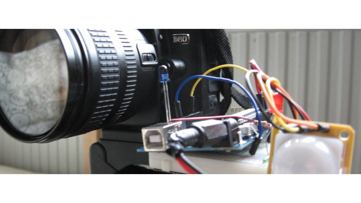
The biggest challenge for this was making sure the camera didn’t keep triggering for the length of time the PIR was active – sometimes it would be active for 5 or seconds after initial movement, so I wanted to capture say 2 photos for each time it was triggered.
For lazyness I’ve left my camera in auto setting so that it *should* autofocus along with everything else – e.g. exposure times and apertures.
Arduino Motion Tracker Parts
220 Ohm resistor (Red, Red, Brown, Gold)
10K Ohm resistor (Brown, Black, Orange, Gold)
PIR sensor
Infrared emitting diode
LED
Arduino Deumilanove w/ ATMEGA328
Breadboard / Prototyping board
Jumper/ Connector wires
Optional 9V power supply (here) or use the USB power for the Arduino
You will also need a soldering iron and solder if you use the same PIR as myself.
The Arduino Motion Detector Circuit
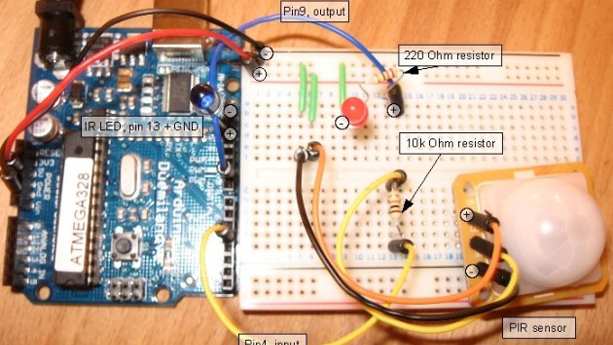
You may not be able to see but I’ve used the power supply from the Arduino to power the breadboard. The PIR gets its supply from this and there’s a 10k Ohm resistor between its output pin and pin 4 on the Arduino. The LED has a 220 Ohm resistor between that and the digital pin 9. The IR LED I’ve left in pin 13 and grounded – for a better system I would solder on a couple of wires to allow more flexibility with transmitting the signal. Also for the PIR, the one I have I had to solder a few jumper wires into the back of it just so you know.
Arduino Motion Sketch / Code
Based off of my remote tutorial I’ve just added in a few extra things really. An output for the LED, an input for the PIR and a chunk of code to limit the taking of photos.
For more detail: Arduino – motion triggered camera
-
How does the PIR sensor work in this project?
The PIR sensor measures any difference to the background temperature and infrared radiation, acting like a switch that turns on when motion is detected. -
What is the biggest challenge mentioned regarding the camera triggering?
The challenge was ensuring the camera did not keep triggering for the full duration the PIR was active, which could last up to five seconds after initial movement. -
How many photos are captured each time the sensor is triggered?
The code is designed to capture exactly two photos for each time the motion is triggered. -
What power source can be used for the breadboard?
You can use the power supply from the Arduino itself, or optionally use a 9V power supply connected to the USB power for the Arduino. -
Why might you need to solder jumper wires to the PIR sensor?
Soldering jumper wires may be necessary to connect the back of the specific PIR sensor model used to allow flexibility with the circuit connections. -
Does the camera autofocus during this setup?
Yes, because the camera is left in auto setting, it should autofocus along with adjusting exposure times and apertures.
