Summary of ARDUINO MEGA FOR BEGINNERS
Arduino MEGA FOR BEGINNERS summarizes the Arduino MEGA board based on the ATmega2560 microcontroller, covering its pinout, specifications, interfaces (UART, SPI, I2C, JTAG, ICSP), PWM and analog pins, power pins, programming via Arduino IDE using C++, and suggested applications. It highlights differences from Arduino UNO and when to choose MEGA for projects needing more I/O or memory.
Parts used in the ARDUINO MEGA FOR BEGINNERS:
- Arduino MEGA development board (ATmega2560)
- ATmega2560 microcontroller IC (100-pin package)
- Power jack (7 to 20V input)
- Voltage regulator (on-board, provides 3.3V)
- Digital I/O headers (54 pins)
- Analog input headers (16 pins)
- PWM-capable digital pins (15 pins)
- UART interfaces (4 UARTs: Tx/Rx pairs)
- SPI interface pins / ICSP header
- I2C interface pins
- JTAG header
In this post I will discuss about the detailed ARDUINO MEGA FOR BEGINNERS. In the previous post I have discussed about brief introduction of the Arduino MEGA there I have discussed about the Arduino MEGA board, specifications of the Arduino UNO, microcontroller IC on which Arduino UNO is based, applications of the Arduino UNO and the programming of the Arduino MEGA.
ARDUINO MEGA FOR BEGINNERS
In this post (ARDUINO MEGA FOR BEGINNERS)I will discuss the overview of the Arduino MEGA board, pinout of the Arduino MEGA, specifications of the Arduino MEGA, microcontroller IC on which Arduino MEGA is based and finally the comparison of the Arduino UNO board with the Arduino MEGA board. So sit back, keep reading and enjoy learning.
Arduino MEGA
- Arduino MEGA is the open-source microcontroller development board based on the ATMEGA 2560 microcontroller IC.
- This microcontroller chip is different from the ATMEGA328P in terms of the digital Input / Output pins, Analog pins and other basic features which will be discussed in detail.
- Arduino MEGA has total 54 digital input / output pins and sixteen analog pins. Note that the Arduino UNO has much lesser Digital Input / Output pins and Analog pins than Arduino MEGA board.
- Arduino MEGA has four UARTS for serial communications, one Serial Peripheral Interface computer bus and one I2C (Inter-Integrated Circuit) computer bus. Out of these 54 digital input / output pins fifteen are PWM (Pulse Width Modulation) enabled pins.
- One additional feature of the Arduino MEGA is that this board also has the JTAG port. The discussion on the JTAG will be followed in the post later.
[otw_is sidebar=otw-sidebar-3]
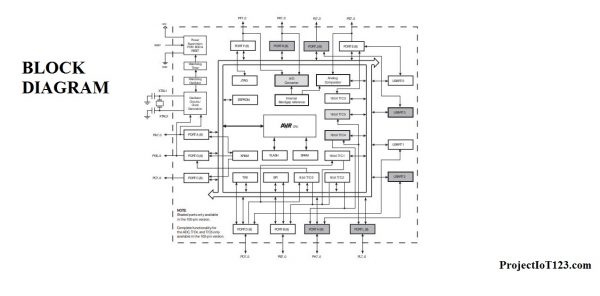
- As described earlier that the Arduino MEGA is based on the ATMEGA 2560 the pinout of the ATMEGA 2560 microcontroller chip is shown in the following figure:

- The microcontroller IC is the 100 pin package and is 8 bit microcontroller chip. Note here that the pin names of the microcontroller IC is different from the pin names of the Arduino MEGA. The detailed discussion of the ATMEGA 2560 is out of the scope of this post anyhow the detailed discussion on the chip will be followed in the later posts.
- The block diagram of the internal architecture of the ATMEGA 2560 microcontroller chip is as shown in the figure below:
Arduino Integrated Development Environment (IDE)
In the post on the Arduino DUE we learned that the Arduino DUE can easily be programmed using the Arduino IDE. The Arduino MEGA can also be programmed in the similar way; that is the programming of the Arduino MEGA is not different from that of the Arduino DUEhowever it should be kept in mind that Arduino MEGA has different number of pins and different pin configuration. The care should be taken while configuring the Arduino MEGA pins. As most of you might have known that in order to program a microcontroller one need to write the code in the editor, and then compile that code in the compiler after which you get the HEX file of that code and later upload that HEX file in the microcontroller IC using another program. In case of Arduino all these steps are performed in single software which is called the Arduino IDE. By integrated Development Environment it means that all the steps that editor, compiler, burner are integrated in the same software. In short Arduino MEGA is quite easy to program it is just a matter of few clicks. I will go through in detail about how to write a code and upload it in Arduino MEGA later in the post.
Arduino MEGA Features[otw_is sidebar=otw-sidebar-2]
- Let us now learn some of the common specifications of the Arduino MEGA microcontroller development board.
- Before diving deep into the discussion it is important to keep in mind that the Arduino MEGA should be used in the case when Arduino UNO does not meet the requirements of the project. For example if one is designing the system in which he / she needs to hook up more than sic analog sensors or needs to interface more number of digital actuators or sensors then he / she should switch to Arduino MEGA otherwise one must stick to the Arduino UNO as Arduino UNO is more economical and easy to handle in terms of space constraints. Let us now have a look on the Arduino MEGA board features.
- Microcontroller IC: Microchip Atmega 2560
- Operating Voltage: 5 Volts
- Input Voltage: 7 to 20 Volts (Note that this voltage would be apply to the jack only and not on the power supply pins available on the header).
- Digital I/O Pins: 54 (of which 6 provide PWM (Pulse Width Modulation) output)
- Analog Input Pins: 16
- DC Current per I/O Pin: 20 mA (This is the current that can be sourced or sink into and out of the Input / Output pins)
- DC Current for 3.3V Pin: 50 mA
- Flash Memory: 256 KB.
- SRAM: 8 KB
- EEPROM: 4 KB
- Clock Speed: 16 MHz (All the operations are synced by this clock)
Note here that Arduino MEGA has all features that are better than Arduino UNO for example the Arduino UNO has 1 KB of the EEPROM whereas Arduino MEGA has four times the EEPROM of that of the Arduino UNO. So these features should be compared while selecting the Arduino board for your system. The detailed discussion on each of the features of the Arduino MEGA is out of the scope of this post however the discussion will follow in the later posts.
Arduino MEGA pinout
- Let us now dive into the discussion (ARDUINO MEGA FOR BEGINNERS)about the pinout of the Arduino MEGA. As described earlier that the Arduino UNO is based on the ATMEGA2560 microcontroller IC
- so it follows that the pinout of the Arduino MEGA is simply that of the ATMEGA2560 microcontroller but note here that the Arduino MEGA has its own nomenclature for its pins and here I will use the nomenclature used by the Arduino for pin reference(ARDUINO MEGA FOR BEGINNERS).
[otw_is sidebar=otw-sidebar-3]

- As pointed out later that the Arduino MEGA has total 54 digital Input / Output pins. The digital Input / Output pins can receive a digital signal or transfer a digital signal.
- The pin number 0 named Rx and pin number 1 named Tx are the receive and transmit pins of the UART (Universal Asynchronous Receiver and Transmitter) respectively.
- The pin number 14, 16, 18 and pin number 15, 17, 19 are also the Tx and Rx respectively so there are total four UARTS on the Arduino MEGA board.
- There are a total of 15 PWM (Pulse Width Modulation) pins present on the Arduino MEGA board. The discussion about the PWM phenomenon and the application of PWM enabled pins will be discussed later.
- Note here that apart from being PWM pins these six pins can also behave like other digital input / output pins.
Arduino MEGA Analog Pins
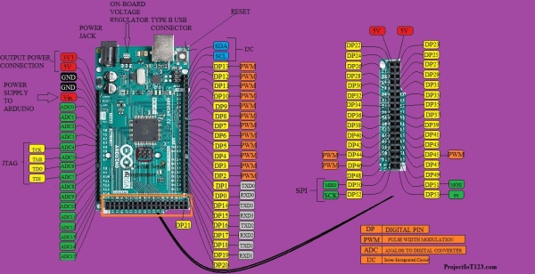
- The headers on the other side are the Voltage header labeled in red and the Analog pins header labeled in Blue let us first discuss Analog pins header.
- The Analog pins header has total sixteen analog pins. Unlike Digital pins these pins can just act as Input pins, that is these pins can only receive signal and cannot provide signal or voltage, that is why they are called Analog inputs.
- These analog inputs are actually the inputs of the Analog to Digital Converter inside the ATMEGA 2560 microcontroller. These pins can be connected to the output of the analog sensors.
- The voltage header consists of pins to which either voltage can be supplied to the Arduino or the pins through which power can be supplied to other peripherals or sensors. Let us now discuss in detail the digital Input / Output pins, Analog input pins and Voltage pins of the Arduino.
[otw_is sidebar=otw-sidebar-3]
Arduino MEGA PWM Pins
- As described in the previous section that the Arduino MEGA has total 54 digital input / output pins out of which 15 input / output pins are PWM enabled.
- The PWM pins are used when the application in hand include speed control or brightness control. Some of these Digital Input / Output pins can also serve as the SPI (Serial Peripheral Interface) or I2C interface (Inter-Integrated Circuit).
- The detailed description is shown in the following figure.
Arduino MEGA SPI Pins
- The function that the digital input / output pins perform depends upon the coding of the Arduino MEGA.
- That is whether the pin number 50, 51, 52 and 53 functions simply as Digital Input / Output or they are used as the Serial Peripheral Interface (SPI) depends upon the coding that specifies their functionality using particular functions.
- It is also important to note here that the Digital Input / Output pins are called as Input / Output because either they can be used as Input in which case they are intended to receive the signals form sensor or transducer (digital) or they can be used as Output in which case they drive the actuators such as relays.
- The functionality of the Digital Input / Output pins as either Input or Output is determined by the code also.
- It is important to realize here that digital input / output pins can only supply a limited amount of current which is not sufficient to drive the motors or relays therefore we need to use drivers such as stepper motor driver or L298 DC motor driver. I will come to the coding of the Arduino MEGA later in this post.
Arduino MEGA JTAG interface
- Let us now learn about the Analog pins of the Arduino MEGA. As described earlier in this post that there are total 16 analog pins present on the Arduino MEGA which acts as input pins only.
- Also we learned that these Analog pins are basically the input pins of the Analog to Digital Converter (ADC).
- These analog pins can receive the analog signals delivered by analog sensors such as Light dependent resistor, thermistor etc. The user can collect data from sixteen different sensors at a time.
- Notice in the image above that the ADC 4, ADC5, ADC6, ADC7 of the Analog pins portion has added functionality that is they can act as JTAG interface.
Voltage Pins
- Let us now discuss another header present on the Arduino MEGA development board. The last pin called the Vin pin is used to connect power supply to the Arduino MEGA.
- That is 5 volt battery or power adapter can be connected to the Arduino MEGA to deliver power through this pin.
- As can be seen in the image that the Arduino MEGA has on board voltage regulator which converts the 5 volts into 3V3 volts.
- The other two voltage pins called 5V and 3V3 are output power supply. That is these two pins can be used delivered power to the peripheral ICs or the sensors that are to be connected to the Arduino MEGA. With the help of these pins the need of additional power supplies is eliminated.
- It is important to note here that the Arduino UNO can supply only limited supply of current through these and if connected to the strong load may damage the Arduino MEGA development board.(ARDUINO MEGA FOR BEGINNERS)
ICSP (In-Circuit Serial Programming)
- Before concluding the discussion on the Input / Output pins it is worth discussing about the ICSP (In-Circuit Serial Programming) pins that are available on the header on Arduino board as shown in the above image.
- As the name implies these pins are used to program the microcontroller chip without the need of taking it out of the circuit. Basically these pins are the SPI computer bus pins that are present on the Digital Input / Output headers.
- They are simply also connected to another header. So these SPI computer bus pins also called ICSP pins here are used to program the microcontroller chip and also used to upload the Bootloader in the new microcontroller chip. The discussion on the Bootloader and how to upload it will be discussed in the next post.
Arduino MEGA Applications:
Before discussing the programming language of the Arduino MEGA let us first know the applications of the Arduino MEGA for motivation. So basically the Arduino MEGA can be used in any system that requires the microcontroller. It is now the most commonly used microcontroller development board that is equally popular among the hobbyists and the engineering students. Some of the embedded systems in which the Arduino can be used are listed below:
- IR remote based Home Automation System.
- Bluetooth controlled Home Automation System.
- IoT enabled Home Automation System.
- RC car.
- Mobile lifter.
- Hurdle Avoiding Vehicle.
- Wall climbing vehicle.
- Autonomous vehicle.
- Robotic arm.
- What is a Thermistor
- How to Simulate Arduino in Proteus
- Arduino Library for Proteus
- Virtual Terminal in Proteus
Arduino MEGA programming language
- One of the perks that make Arduino MEGA quite popular among the hobbyists and beginners is its easy to use programming language and programming.
- The programming language used by the Arduino MEGA is the C++. The Arduino MEGA IDE has a well-defined function for each task that is easy to remember. As an example the function that specifies the Arduino MEGA digital Input / Output pin to work as input is :
[otw_is sidebar=otw-sidebar-2]
pinMode(12,INPUT);
Here in this function there are two arguments. First argument is the pin number which we want to make input or output and second argument specifies the property that is input or output to the pin number used. The detailed discussion on programming the Arduino MEGA will come later in the next posts.
That is all for now I hope this post would be helpful for you. In the next post I will come up with more interesting topics. Till then stay connected, keep reading and enjoy learning.
Source: ARDUINO MEGA FOR BEGINNERS
- What microcontroller IC is Arduino MEGA based on?
Arduino MEGA is based on the Microchip ATmega2560 microcontroller IC. - How many digital I/O and analog input pins does Arduino MEGA have?
Arduino MEGA has 54 digital I/O pins and 16 analog input pins. - Does Arduino MEGA support PWM and how many PWM pins are there?
Yes, Arduino MEGA has 15 PWM-enabled pins out of its digital I/O pins. - Can Arduino MEGA be programmed using the Arduino IDE?
Yes, Arduino MEGA can be programmed using the Arduino IDE similarly to other Arduino boards. - What communication interfaces are available on Arduino MEGA?
Arduino MEGA provides four UARTs, one SPI bus, and one I2C bus. - What is the operating voltage and input voltage range for Arduino MEGA?
The operating voltage is 5 volts and the input voltage range via the jack is 7 to 20 volts. - What memory specifications does Arduino MEGA have?
Arduino MEGA has 256 KB flash memory, 8 KB SRAM, and 4 KB EEPROM. - When should one choose Arduino MEGA over Arduino UNO?
Choose Arduino MEGA when a project needs more analog inputs, more digital I/O pins, or greater memory than Arduino UNO provides. - What are the power output pins available on Arduino MEGA?
Arduino MEGA provides 5V and 3V3 output pins and a Vin input pin for supplying power. - What is the clock speed of the Arduino MEGA?
The clock speed of Arduino MEGA is 16 MHz.