Project and Instructable write-up done by Ian Lacy on behalf of the MIT Edgerton Center.
In this project, I’ll show you how to build an Apollo 11 clock. The clock has each hour associated with a leg of the mission, and plays an associated audio clip at each hour. Every third hour, it also has a motion associated with that leg of the mission!
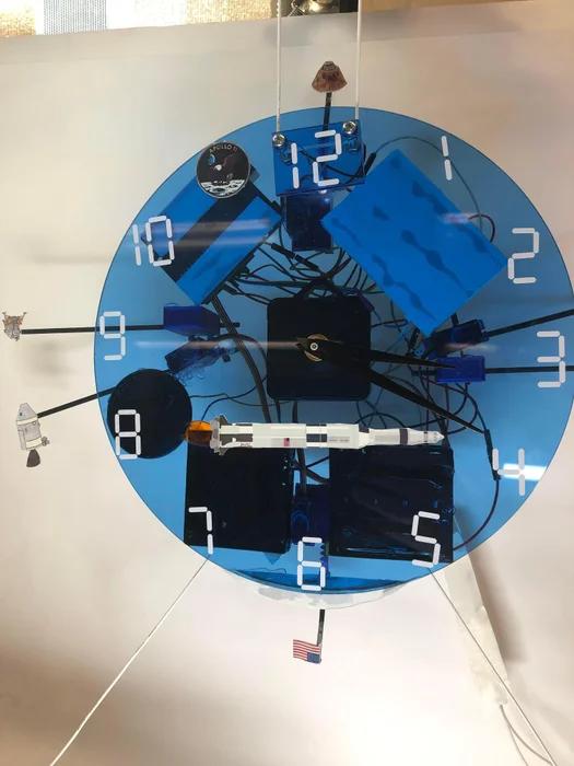
Though my clock has a pretty specific theme, the idea can be broadly generalized, and adapted to almost any theme you want! I’ll be sure to point out the important parts of generalizing the idea, and how to make the most of the design.
Supplies
Materials for clock face (I used acrylic)
3.3V white LED
Photoresistor (any)
1/8” dowel rods
Cardstock or paper
Sticker vinyl
Clock movement
Breadboard
Arduino Uno R3
4 x small servo
DFRobot DFPlayer Mini
2 x small switches
Small button
2 x 4 x AA battery pack
Tools:
Basic craft tools
Printer
Miscellaneous jumper wires
Recommended:
Soldering Iron
Laser cutter
Vinyl cutter
The Arduino code is attached here as well as in the code/troubleshooting step.
Step 1: Design
The most important step in any project is the design and planning phase. To end up with a great end result, you first have to make a good plan. Sometimes the planning phase happens repeatedly, with prototyping in between, but a thorough design and plan is necessary before making the final product.
Working off the idea of ‘clock that makes noise,’ the first thing you need to do is choose a theme. The theme I chose was Apollo 11.
The next thing you may want to do is find something about your theme that can be broken into 12 parts, but this isn’t entirely necessary. I assigned each hour to one leg of the Apollo 11 mission, which coincidentally worked out well. (i.e. 1 is launch, 6 is the landing, etc)
You’ll then want to go through and pick a sound or audio clip for each of your 12 hours.
You also will want to come up with four things the motions can do! I’ll describe mine as they come up.
If you want to follow my steps, or just want some inspiration, here is the google doc I used to plan things.
Step 2: Audio
Setting up the audio is the part that’s almost entirely on the computer. Once you’ve chosen your 12 sounds/clips, you’ll want to get them at .mp3 files on your computer.
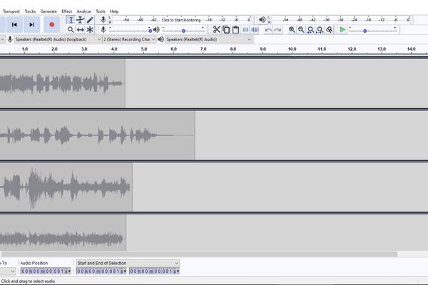
To do this, you can download them from royalty-free sites, or use any other method. To get my clips, I got screen recording software, went to the Apollo in Real Time site, found audio clips I wanted to use for Apollo 11, and then recorded my computer playing them. I then extracted the audio using Audacity, trimmed it, and exported it.
The last step is to name the files ‘XX.mp3’ where XX is the number you want the file to play at. The file for 1 o’clock will be ‘01.mp3’ for example.
You’ll then copy these files to a blank microSD card, making sure they appear in numerical order.
Here is a compressed folder with the audio clips I used as well as the audacity project I exported them (one channel at a time) from
Step 3: Clock Face
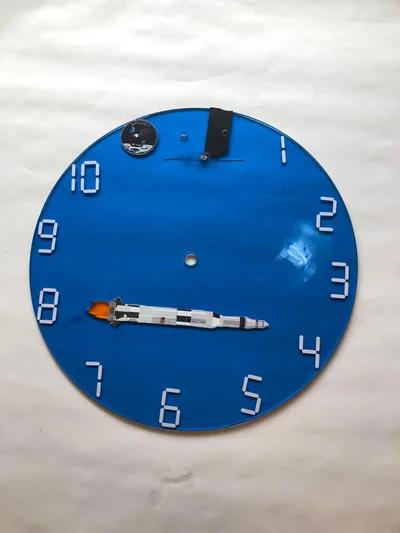
The first physical part of this project is making the clock face. For my clock, I laser-cut a 9″ circle out of acrylic, but anything with enough clearance for the hands of your clock should work equally well. This could be plywood, acrylic, or even a plastic plate.
I also cut a small fire-shaped hole out and filled it with orange acrylic to be used as the fire for the booster.
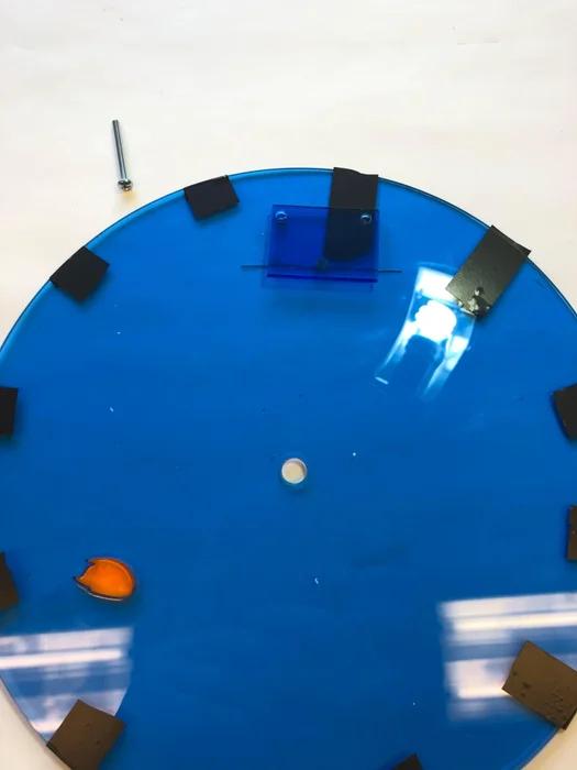
Your clock face will need a hole for the shaft of your clock movement (in my case, ⅜”) at the place you want your clock hands to be centered on.
After you’ve made your center hole, lay your minute hand so its hole is centered over the hole in the clock face, and mark/drill two 1/16” holes about 1/4” from the end tip of the hand. The photoresistor will slot through this hole.
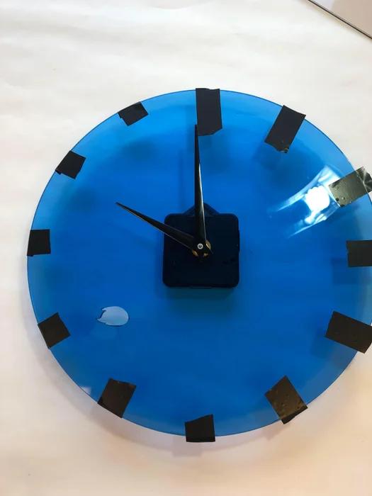
You can then decorate your clock with numbers, stickers, or other decals, so long as they won’t impede the hands of the clock or the photoresistor. It helps to mark the clock at 30 degree intervals– the best way I have found to do this is to find your 12 o’clock spot, mark it, and then install just the movement (see step 8) and then start both the hour and minute hands on 12. Then manually advance the clock by an hour, so the minute hand lands back at 12, and use a ruler to mark where the hour hand lands. Repeat for each hour.
Step 4: Sensor Standoff
For the Arduino to know when the minutes hand passes 12, we need to make a sensor.
- Make a ~1.5” x 2” piece of your material.
- Find a drill bit that is slightly wider than the thread on your bolts. Drill holes in the top corners of the small piece you made.
- Line it up so the long edge is a bit below the photoresistor, square it up (make the wide side perpendicular to the direction of the minute hand) and mark and drill two bolt-sized holes in the clock face.
- (Optional) If you have a soldering setup, you can solder wires to the legs of the LED like i did, which will let you use the bolts as pass-throughs. This means no wires going around the back! Be sure to note which leg is the positive leg.
- Bend the legs of your white LED so that the legs will lie against the piece and the light will point away from it, as shown.
- If you didn’t do step D, place the female end of an M/F jumper on each leg of the LED. I suggest color coding- put a black jumper on the negative shorter leg (the leg on the side that has a flat spot on the housing) and a red jumper on the positive longer leg.
- Line the piece up with the holes in the clock face, and note where the photoresistor falls under it. Use tape or glue to attach the LED to the underside of the piece, so that when it’s bolted on it lines up with the photoresistor and illuminates it
- Place the bolts through the front of the piece, and tighten nuts onto the back of the piece. If you did step D, wrap each lead clockwise around the bolts. The nut should tighten down over the leads and make a good electrical connection. Afterwards, trim the wires.
This LED standoff, combined with the photoresistor you installed in step 2, will serve as a way for us to sense when the minute hand passes 12.
Step 5: Set Up Servos
In my project, I have two kinds of motion- linear, and rotational. For your project, you can add whatever motion you want, but I’ll be demonstrating how I did mine.
First type- rotational. The 3 and 6 servos will move dowel rods holding paper decals. They will be set up to meet stationary decals.
Print your decals on cardstock, and then using white glue, layer an additional sheet of cardstock onto the back. Use scissors or a hobby knife to cut out the decals. Paint thin dowel rods to hold each of the decals, and then glue the decals on.
Use small cable ties to strap the moving rod to the arm of the servo. To hold the other rod, I’ve made a small holder on tinker cad. (STL attached) You can make your own, depending on your project, or modify the one I’ve made. The other rod will rest on top, and cable ties will loop over it through the small holes.
After both rods are secured, position them where you want them, and stick them to your clock (Hot glue tends to work, in my experience). Make sure they’ll interact how you want- you can, of course, change the code to get the right speed and range of motion for your servos.
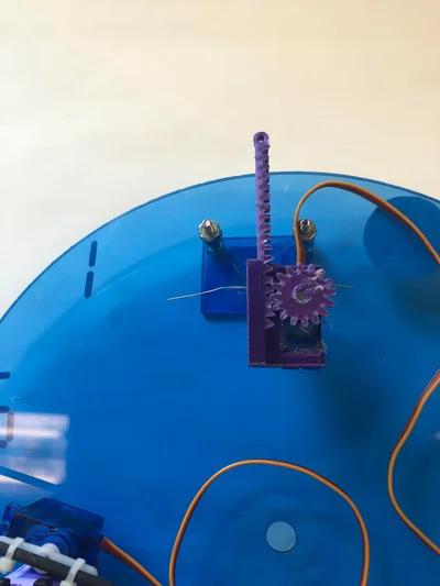
The second type of motion is linear. To achieve linear motion, I snagged a linear actuator adapter off of thingiverse and scaled it in the slicer so that it would fit the servos I’m using. The base decal (for 6 for example, the moon) will be attached directly to the clock, and the moving decal will be stuck to a rod, as with the rotational motion, which is then strapped to the pinion of the linear actuator with cable ties. Position the servo so that the rod lines up how you want, and then stick it down. You can move the pinion around to set the starting height, and modify the code to change the range of motion.
Step 6: Wiring
There’s unfortunately a LOT of wiring for this project, but if you happen to have Fritzer, I’ve uploaded the .fzz file for your use. If you don’t, no worries! I have several pictures.
Largely, the wiring can be done however you want. I’ll be showing you my method, but as long as the connections end up right, it’s entirely your choice as to how to accomplish it.
Additionally, the last step of this instructable explains some wiring hacks that I used to clean up/simplify the wiring on my build. These require solder and a bit of creative methodology, and thus are a bit more advanced than this instructable is meant to be, so they’re entirely optional.
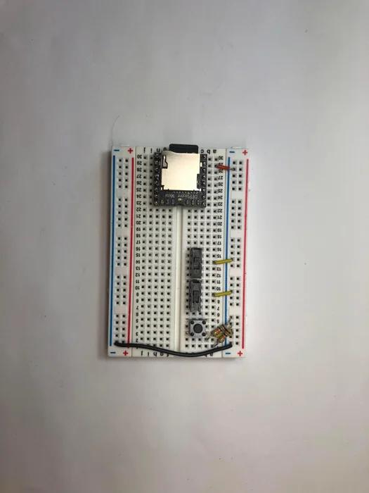
The first part of the wiring to be done is to load up the breadboard. Stick the DFPlayer on one end, making sure it goes across the slot so each pin has its own row on the breadboard. Then, place two switches and a button on the breadboard, as shown. Pick two rows for your LED and photoresistor, and for each of them bridge a 10 kΩ resistor to the negative rail. Next, bridge one side of your button, the common terminal of each switch, and the GND pin of the DFPlayer to the negative rail with a jumper wire. Next, use a jumper wire to bridge both negative rails together.
Now that the breadboard is set up, you can mount it, the Arduino, and your speaker to the back of your clock face. You can also now mount the 2 x 4 x AA battery packs at any time, though I held off on them until the end.
Next, we need to hook the Arduino to the breadboard. The first set of hookups is as follows:
Arduino -> breadboard
Vin -> positive rail (the one that will have the batteries)
5V -> other positive rail (the one that will power the LED and photoresistor)
3.3V -> DFPlayer Vcc
GND -> negative rail
That’s the power hook-ups done!
Now for the input hook-ups:
A0 -> photoresistor pulldown resistor
6 -> button (the side that’s NOT bridged to negative rail)
7 -> switch you want to use for mute
8 -> switch you want to use for freeze
That’s the logic/inputs done!
For the DFPlayer:
10 -> DFPLayer TX
11 -> DFPlayer RX.
You’ll then jump leads from your speaker to the SPK_1 and SPK_2 pins on the DFPlayer.
To hook up the LED, run the negative leg of the LED to the current-limiting resistor you hooked up earlier, and run the positive leg of the LED to the positive rail you jumped the 5V from the Arduino to. To hook up the photoresistor, run one leg to positive and one leg to the slot that has the jumper to A0 and the pulldown resistor. The legs are interchangeable.
Now, all that’s left is the servos. Run the power lead of each one (normally the red) to the positive rail that is hooked to the batteries. Run the ground lead of each (typically brown) to either negative rail. Finally, hook the control wires up to the arduino:
2 -> 3 o’clock servo
3 -> 6 o’clock servo
4 -> 9 o’clock servo
5 -> 12 o’clock servo
If you haven’t hooked up the batteries yet, BOTH positive leads will go to the battery positive rail, and BOTH negative leads go to the negative rail. These battery packs are in parallel to make sure that the servos won’t brown out the board. It also allows for expansion with additional servos, LEDs, or other functions.
You’re done with the wiring! Getting close to being done fully, too. Double check your wiring, and then you can upload the Arduino code, and test the clock. The switches should turn off the sound and motion respectively, and the button should advance the time when you push it.
Step 7: Installing the Clock Movement
The last step is to put in the clock movement. The movement should come with instructions, but the basic process is usually the same. Make sure to remove the nut and top washer from the movement, then insert it from the back of the clock. Put the top washer over it, and then tighten down the nut. Install the hour hand, then the minute hand, then the seconds hand (I left mine off because it was a bit beat up). After this, you’ll want to run it a few times around with the time setting mechanism to make sure the hands all clear the sensor/LED. If they don’t, adjust the nuts on the standoff to get the height right. After it all fits, you should be good to go! Power on the clock and test it out.
Step 8: Code/Troubleshooting
To make sure everything is working, power on your clock and use the button on the breadboard to advance the clock through each of the hours. Make sure the
A few words on troubleshooting- the issue you’re most likely to run into is that the clock either doesn’t trigger when it should, or triggers when it shouldn’t. The first thing you should try in this case is the threshold definition in the code. Since the ambient lighting is different for everyone, the values the photoresistor outputs varies from person to person. To know where to set the threshold, connect the Arduino to your computer, and then open the serial monitor. Check the output value for ambient light conditions, and the output value when the minutes hand is covering the sensor, and set the threshold slightly above that value. If they’re too close together, consider changing the standoff height, changing the clock movement, or finding a brighter LED (or slightly reducing the resistance of the LED resistor (from 10k to 8k, for example)
Another issue would be the servos twitching or the board resetting. Make sure your batteries are fresh– having the parallel packs should mean the servos have enough current capacity to draw from, but dead batteries would hinder that.
If you’re having audio problems, make sure the files are named right and are .mp3 files. If it still won’t play, try downsampling it in audacity. Also, make sure the RX and TX wires are in the right spot- if the DFPlayer doesn’t activate, try swapping them.
To skip or modify the servos, you’ll find their programming in the movement() function at the bottom. To change what time they activate at, change the case. To change how they move, modify the for loop. To prevent twitching, make sure to detach them after you’re done moving them. To fully remove them, you can either delete the code block, or change the case number to something higher than 12.
Step 9: Wiring Hacks
Since there’s so many wires, it can be handy to consolidate some of them.
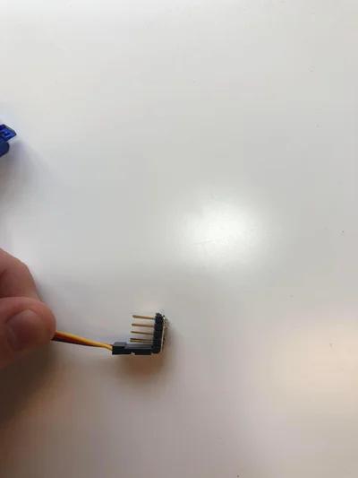
One thing I did that you can do too is bus the servos together. I used a 2×5 header piece, but you can use two 1×5 header pieces. Use a wire and some solder to make each row into a bus, and then you can rack the servos together- one bus will be negative, one positive, and the last pin on each bus is used to jump it to power.
The other thing I did was use some headers and some ribbon cable to make a ribbon for the servo and for the switches/button. Solder the ribbon wires to the header pins, and then you can insert those into the Arduino. Do the same on the other end and those can end up in the breadboard or the servos, or anything else you need them in. After that, you’re all set!
Source: Apollo 11 Arduino Clock