
Summary of Analog audio panel for PC using Arduino
This article describes a DIY analog audio control panel built with an Arduino UNO shield to manage VoIP call settings like mic volume, speaker volume, and mute functions directly from the desk. The project replaces software fiddling with physical controls, including VU meters, touch switches for input/output selection, and a buzzer for feedback, offering instant access to audio adjustments during remote conferences.
Parts used in Analog Audio Panel for PC:
- Arduino UNO
- Breadboard
- Wires
- Eagle files (schematics and PCB designs)
- Two VU meters (red bar and green bar)
- Analog mic volume control
- Analog speaker volume control
- Touch switch for selecting mic inputs
- Touch switch for selecting speaker outputs
- Touch switch for mic mute/unmute
- Buzzer
- Display unit
Have you ever struggled with audio settings in control panel in middle of a VoIP call? Or, wondered if the other guy can hear you properly? I have. My work requires great deal of remote conference calls using PC. The first thing I wonder always when starting is if my audio settings — mic volume, input selection, mute/unmute, speaker volume — are in order. Typically, they are not and it takes a while to fiddle them right. Even just controlling volume from desktop panel isn’t conveniently quick enough.
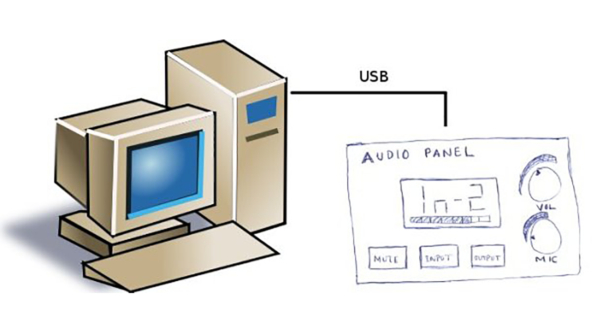
What if you had the audio control panel, the dialog in most PCs where you fiddle audio, right next to your PC in physical form? With analog controls, VU meters and input/output selection present for instant access on your desk, you will have the pleasure of controlling them with hand.
I have been meaning to complete this project for some time, but it took a while to get all the parts ordered and PCB fabricated. Finally, it’s coming together now.
If you came across this blog post by accident, then you most likely know Arduino :). For those who don’t, it’s an open source microcontroller platform based on an Atmel’s 8 bit microcontroller (ATMega328p, specifically) and is incredibly popular among electronics hobbyists for its simplicity and versatility.
Electronics
The humble start was, of course, with a breadboard and spaghetti of wires 🙂
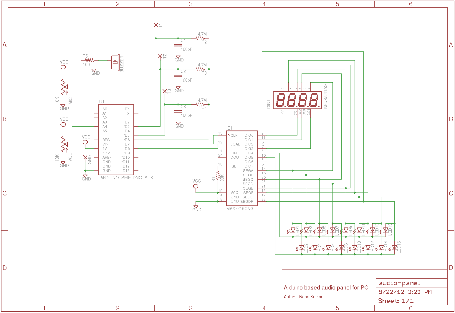
Schematic below shows how the electronics is implemented. All of the hardware and software is open source, so the eagle files containing schematics and PCB designs can be downloaded from sourceforge project site (once I create the project :)).
- Two VU meters – red bar and green bar for microphone level
- Analog mic volume control
- Analog speaker volume control
- Touch switch for selecting mic inputs
- Touch switch for selecting speaker outputs
- Touch switch for mic mute/unmute
- A buzzer to beep for touch feedback.
- A display to show input or output selection.
For more detail: Analog audio panel for PC using Arduino
-
What is the main purpose of this project?
The project provides a physical analog audio control panel on the desk to instantly manage microphone and speaker settings during VoIP calls. -
Which microcontroller platform does this project use?
It uses the Arduino platform based on an Atmel 8-bit microcontroller, specifically the ATMega328p. -
How are the audio settings controlled physically?
Settings are controlled using analog knobs for volume and touch switches for input selection and muting. -
Does the device provide visual feedback for audio levels?
Yes, it features two VU meters consisting of red and green bars to show microphone levels. -
How does the user know if a touch switch was activated?
A buzzer beeps to provide tactile and auditory feedback when a touch switch is used. -
Where can the schematic and PCB design files be found?
The open source Eagle files containing schematics and PCB designs are available on the SourceForge project site. -
What specific functions do the touch switches perform?
The touch switches handle selecting mic inputs, selecting speaker outputs, and toggling mic mute/unmute.
