
Summary of 5X5 dot matrix on Arduino
This project demonstrates a DIY 5x5 LED dot matrix display controlled by an Arduino Uno. Users input text via computer to display messages on the matrix. While not highly practical, the build is rewarding and involves wiring LEDs with resistors and basic scripting. The article details the necessary components, connection diagrams, and step-by-step assembly instructions for creating this custom display unit.
Parts used in the 5x5 Dot Matrix Display:
- 25 LEDs
- Breadboard
- Arduino Uno
- Sharp nose pliers (optional)
- 5x 100 ohm resistors
With this you just type the text you want on your computer and your 5×5 dot matrix shows the message.
Used:
~25 leds
~Arduino uno
~5x 100ohm resistor
~and a bit of skripting
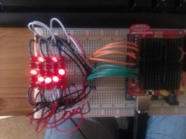
It took me a while to figure this all out but in the end it was quite rewarding. not really practical though. 🙂
Enjoy.
Plz comment and let me know what you think.
Step 1: You wil need..
25 leds
Breadboard
Arduino- have the uno-
Sharp nose [liers for hard to reach places (optional)
5×100 ohm resistors (brown black brown)
Step 2: Diagram
I know it looks sideways but this is how i connect it to my Arduino
Step 3: Starting with connections
Here is how i coneckted the leds. it gets a bit conplecated but works. feel fre 2 try own metheds
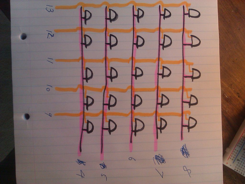
I made it that all the anodes are connected down, like in the pic. the cathodes are so that only 2 are connected. The one on the left shears a line with the one on his right.
Step 4:
The catrodes are then connected to allow a horizontal connection as n the photo.
I just wired them all to a neutral location so that can connect them to my arduino easier
Step 5: To Arduino
now just connect according to the diagram with the resistors on the cathrodes.
Breadboard
Arduino- have the uno-
Sharp nose
For more detail: 5X5 dot matrix on Arduino
-
What components are required to build the 5x5 dot matrix?
You need 25 LEDs, a breadboard, an Arduino Uno, sharp nose pliers, and five 100 ohm resistors. -
How does the user input text to the display?
The user types the desired text on their computer, which then appears on the 5x5 dot matrix. -
Where should the resistors be placed in the circuit?
The resistors are connected to the cathodes when connecting the LEDs to the Arduino. -
How are the anodes of the LEDs connected?
All anodes are connected downwards as shown in the project photos. -
How are the cathodes arranged in the matrix?
The cathodes are connected so that only two are linked, allowing for horizontal connections. -
Is this project considered practical for daily use?
No, the author notes that while the project is rewarding, it is not really practical. -
What tool is optional but helpful for hard-to-reach places?
Sharp nose pliers are listed as an optional tool for difficult connections.
