In some point in the life of every electronics hobbyist the need to make a clock is borned, in my case it was about a month after I soldered my first part on a board, but back then I didn’t have the right tools, parts and knowledge to do such a thing.
But after about 2 years I got all the things I didn’t have back then and I was ready to make my first digital clock, and with all the LEDs I had left over from my 8x8x8 LED cube project I decided to make my own custom LED clock.
So join me and build your own custom LED digital clock powered by our favorite little micro-controller the Arduino.
Step 1: What Do We Need?
Here is what tools you will need to make this:
1) Soldering Iron.
2) Some solder wire.
3) Small needle nose plier
4) Small cuter
5) Wire striper
I made my clock with a stand alone arduino without the original board because I wanted to make a finished project.
Now here are the parts you will need to make the clock:
1) 130 LEDs.
2) 15 2N4401 transistors.
3) 20 1K resistors.
4) about 10 resistors for the current protection(more detail in step 2). I used 150Ohms.
5) DS1307 real time clock IC.
6) one coin cell battery holder.
7) 4 Tact switches.
8) Prefboard (you would like to get along one for the display about 8inch*3inch)
9) ATMega328 with arduino bootloader.
10) A programmer for programing the chip.
11) 7805 voltage regulator.
12) 16MHz crystal.
13) two 22pF caps.
14) 28 pin IC socket for the ATMega328.
15)10 uF cap.
16)0.1 uF cap.
17) 4017 counter
18) 32.768KHz crystal
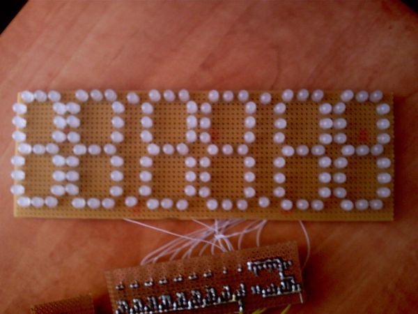
Step 2: The Seven Segment Display
The clock is made of six seven segment displays which make up the display.
Each digit made of seven segments and every segment made of 3 LEDs in parallel.
So a simple calculation gives that there are 21 LEDs in each seven segment display.
And all six digits take 126 LEDs.
But as I said In the parts list you will need 130 LEDs and the other 4 LEDs are going to be used as dots that separate the hours, minutes and the seconds.
I made a common cathode display which means the all the negatives leads are connected together.
Now you will need to choose the right resistor for current limiting to 3 LEDs in parallel.
The calculation is simple and gos like this :
R=(Vcc-Vled)/(Iled*3)
R= the resistor value
Vcc = The voltage that is supplied
Vled = the forward voltage on the LED
Iled =the current the LED takes
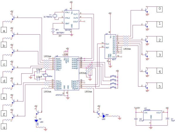
Step 3: So How It Works?
This kind of display calls for a large amount of pins to power it out so a special technique is needed.
I used multiplexing.
Multiplexing works by switching between the digits one by one very fast and by so creating a illusion that all of the displays are working in the same time.
This works by connecting each segment to the same one on a different digit and by so you will have only seven segments that are all the same for all the digits.
And you can choose what digit you want to power by connecting the negative leads of the display to ground and sending the data to the positive segment leads.
The scanning of the display is accomplished by the 4017 decade counter because I wanted to save some pins on the arduino, to control it you will need just 2 arduino pins.
The 4017 connects the grounds one by one and by so it scan the display[box color=”#985D00″ bg=”#FFF8CB” font=”verdana” fontsize=”14 ” radius=”20 ” border=”#985D12″ float=”right” head=”Major Components in Project” headbg=”#FFEB70″ headcolor=”#985D00″]30 LEDs.5 2N4401 transistors.20 1K resistors.1307 real time clock IC.one coin cell battery holdeThis kind of display calls for a large amount of pins to power it out so a special technique is needed.
I used multiplexing.
Multiplexing works by switching between the digits one by one very fast and by so creating a illusion that all of the displays are working in the same time.
This works by connecting each segment to the same one on a different digit and by so you will have only seven segments that are all the same for all the digits.
And you can choose what digit you want to power by connecting the negative leads of the display to ground and sending the data to the positive segment leads.
The scanning of the display is accomplished by the 4017 decade counter because I wanted to save some pins on the arduino, to control it you will need just 2 arduino pins.
The 4017 connects the grounds one by one and by so it scan the display[/box]
For more detail: Make A Digital Clock From Scratch using arduino