Summary of Weather Monitor
This article details the construction of an Arduino Uno-based weather monitoring device. The system measures temperature and barometric pressure using a BMP085 sensor, displaying data on a 16x2 LCD when a button is pressed. It requires soldering skills and C programming knowledge for customization. The project involves assembling a sensor box for the BMP085 and a control box housing the microcontroller, display, and power supply.
Parts used in the Weather Monitor:
- Arduino Uno R3 Microcontroller Board
- Gleichmann GE-C1602B-TFH-JT 16x2 LCD
- Bosch BMP085 Barometric & Temperature Sensor
- Energiespar-Steckernetzteil USPS-600 Power Supply
- Spelsberg TK Plastic Housing (180 x 94 x 57 mm)
- SCI Illuminated Push-Button
- Duo-LED Status Indicator (Red/Green)
- 10K Potentiometer
This Instructable shows you how to build a micro-controller based weather monitoring device. Built on the Arduino Uno board it can easily be extended and modified should you have additional sensors at hand.
Main requirements:
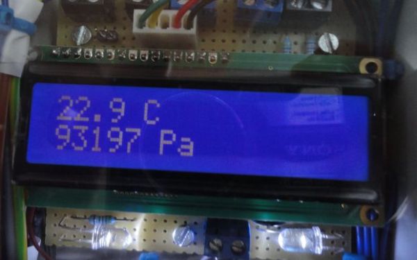
– Measure temperature (accuracy +/- 0,5 degree Kelvin)
– Measure barometric air pressure (+/- 0,1 Pascal)
– Display measured values on a LCD on demand by pressing a button
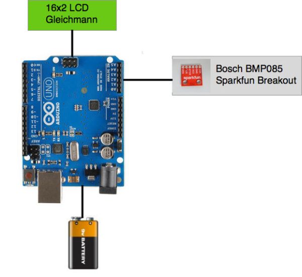
Main components:
– Arduino Uno board as controller unit
– 16×2 LCD for data output
– BMP085 Sparkfun breakout board as sensor unit for barometric pressure and temperature
In order to build this device some experience with soldering is required. Especially the wiring of the LCD and the Sparkfun break-out need to be soldered carefully.
Experience with Arduino Boards is also required and some C-Programming is needed should you want to modify the sources provided or if you have only different components available.
In order to run the Weather Monitor you have to build up the following components:
– A Sensor Box for the barometric/temperature sensor
– A Control Box containing the Arduino board, the LCD and connects to the sensor box
– The Arduino control software which controls the operation of the system
Step 1: Required Components
List of System Components
- Microcontroller Board: Arduino Uno R3
- LCD: Gleichmann GE-C1602B-TFH-JT/R
- Barometric & Temperature Sensor: Bosch BMP085
- Power Supply: Energiespar-Steckernetzteil USPS-600, Voltcraft
- Housing: Spelsberg TK Kunststoffgehäuse 180 x 94 x 57 mm plus Montageplatte
- Illuminated Push-Button: SCI Drucktaster 250 V/AC 0,5 A beleuchtet R13-529ALBL 1x Aus/(Ein)
- Status LED: Duo-LED 5 mm CQX 95 / WU-1-91EWG Rot, Grün 60 ° Gehäuseart 5 mm 90/70 mcd
Depending on your preferred method to connect the components you may need additional wiring or a breadboard.[/su_box]
Step 2: Electrical Wiring
This section lists the required wiring. There is currently no graphical schematic available, but I hope it is possible for you to connect up the components based on the following listing:
==============================
Summary on Arduino Pins
————————–
A0 —> PushButton Manual OP
A1 —> PushButton LED Manual OP
A2 —> Operation Panel LED RED
A3 —> reserved
A4 —> BMP085
A5 —> BMP085
0 —> reserved
1 —> reserved
2 —> LCD
3 —> LCD
4 —> LCD
5 —> LCD
6 —> Illumination LEDs and LCD Backlight
7 —> Operation Panel LED GREEN
8 —> LCD
9 —> LCD
10 X reserved for Ethernet/SPI
11 X reserved for Ethernet/SPI
12 X reserved for Ethernet/SPI
13 X reserved for Ethernet/SPI
==========================
BMP085 —> Arduino Uno
————————–
VCC —> 3.3V
GND —> GND
SCL —> A5
SDA —> A4
===========================
Arduino —> LCD 16×2
—————————
GND —> Gnd (pin 1)
5V —> VCC (pin 2)
digital 9 —> RS (pin 4)
GND —> R/W (pin 5)
digital 8 —> E (pin 6)
digital 5 —> D4 (pin 11)
digital 4 —> D5 (pin 12)
digital 3 —> D6 (pin 13)
digital 2 —> D7 (pin 14)
digital 6 —> Backlight (pin 15)
Arduino –> 10K Poti –> LCD
——————————
Poti-ends to +5V and Ground
Wiper —> LCD VO (pin 3)
==============================
Arduino —> Illumination LEDs
——————————
digital 6 —> White LEDs PLUS (PWM)
GND —> White LEDs MINUS
==============================
Arduino —> Operator Panel
——————————
A0 —> PushButton Manual OP
A1 —> PushButton LED Manual OP
A2 —> Operation Panel LED Error
digital 7—> Operation Panel LED OK
Step 3: Assembly of Sensor Box
Take care when mounting the connector strip to BMP085 breakout board. Try to avoid too much heat during soldering since the sensor readout may become unstable.
In order to operate the BMP085 outside a building it needs to be put into a casing to protect its electric circuit.
A fluffy housing for the sensor board ensures a stable measurement of barometric pressure.
Nevertheless the casing should allow air circulation in order to timely measure of temperature and correct measurement of the air pressure.
Step 4: Assembly of Control Box
The suggested casing allows to mount the Arduino board and additional connectors on the bottom of the casing. First picture above show a suggested layout before mounting the LCD. Connect the Arduino, LCD and BMP085 as listed in Step 2. Additionally I added a operation button and a status LED for manual operation for more convenience and feedback.
Instead of a battery I recommend to use a DC power supply shown above, which is available for less than 10 EUR.
For more detail: Weather Monitor
- What are the main measurement requirements?
The device must measure temperature with +/- 0.5 degree Kelvin accuracy and barometric air pressure with +/- 0.1 Pascal accuracy. - How do you trigger the display of measured values?
Measured values are displayed on the LCD on demand by pressing a specific button. - Which components require careful soldering?
The wiring of the LCD and the Sparkfun breakout board for the sensor need to be soldered carefully. - Can this device be extended with additional sensors?
Yes, the design built on the Arduino Uno board can easily be extended and modified if you have additional sensors. - What software is needed to modify the system?
C Programming experience is needed if you want to modify the provided source codes or use different components. - Why is a casing required for the BMP085 sensor?
A casing protects the electric circuit from the outside environment while allowing necessary air circulation for accurate measurements. - What type of power supply is recommended instead of a battery?
A DC power supply like the Energiespar-Steckernetzteil USPS-600 is recommended as it costs less than 10 EUR. - What is the function of the 10K Potentiometer?
The potentiometer connects to the LCD VO pin to adjust contrast between +5V and Ground.