Summary
In this undertaking, we’ll employ an HC-05 Bluetooth module alongside a smartphone for transmitting vocal instructions to oversee LEDs and to accept voice directives. Our approach involves utilizing an “Arduino Bluetooth Voice Controller” Android application, readily downloadable from the Play Store. The microphone captures spoken input, which is subsequently processed by the voice module through voice commands. These voice commands are issued via the mobile device to the Bluetooth setup, which possesses specific functionalities for regulating the activation and deactivation of individual LEDs.
Objectives
- Acquiring the skill of utilizing the HC-05 module to govern Arduino through Bluetooth communication.
- Gaining proficiency in managing LEDs through the amalgamation of Bluetooth modules and Arduino.
Applications in Various Industries
Automation holds a pivotal position in the realm of technology. Home automation facilitates the management of household electrical devices like lights, doors, fans, air conditioning, and more. Additionally, it enhances home security and establishes an emergency response mechanism. Home automation not only lessens human exertion but also contributes to energy conservation and time efficiency. The central aim of home automation and security is to assist individuals with disabilities and the elderly, empowering them to oversee home appliances and receive alerts during crucial circumstances.
Project Methodology
Voice control entails the utilization of speech recognition technology, wherein the system comprehends spoken words. The primary objective of this endeavor is to govern LEDs through human vocal commands. Within this setup, a voice recognition module has been employed to identify user speech, thereby facilitating the toggling of LED states. The evolution of this project’s application extends to the management of household devices via voice directives, thus rendering it a potential home automation solution. The commands are programmed into the Arduino board. Home appliances can be managed through two avenues: vocal instructions or employing a mobile device as a remote controller.
Arduino, a user-friendly integrated development environment, is harnessed for crafting programs in C or C++ languages, which are then loaded onto the Arduino controller to execute various commands.
Components:
- 1x Arduino Uno
- 1x HC-05 Bluetooth Module
- 3x 330 Ohm Resistors
- 3x LED’s
- Jumper Wires
- 1x Breadboard
Project Procedure
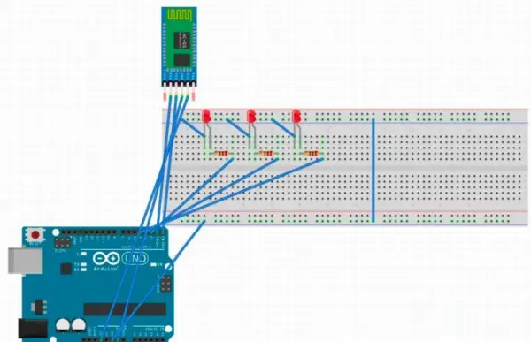
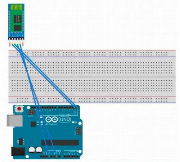
The HC-05 Bluetooth module, in its standard configuration, incorporates six pins. Nonetheless, for the scope of this project, our focus will be on four particular pins: VCC, GND, TXD, and RXD.
The Bluetooth module’s VCC pin establishes a connection to the Arduino’s +3.3V input. The module’s GND pin links to the Arduino’s ground. Connecting to digital pin 0 (RXD), the module’s TX pin completes its circuit, while the RXD pin interfaces with digital pin 1 (TXD).
Moving forward with our voice-controlled LED setup, proceed to establish a connection between the LED and the Arduino using the breadboard. Initially, link the LED’s shorter terminal to the ground. Then, connect the longer terminal of each LED to a 330-ohm resistor.
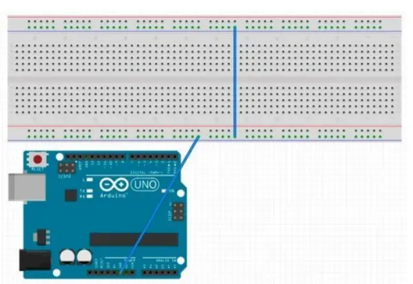
A +5V power supply can be directed to the Arduino using various means. Employing a USB port from your computer is a convenient option. However, before introducing power to the Arduino, it’s imperative to confirm the connection between the Arduino’s GND and the breadboard’s ground.
Code:
#include <SoftwareSerial.h>
SoftwareSerial BLU(0,1);
String voice;
int Green = 4; //Connect To Pin #4
int Yellow = 2; //Connect To Pin #2
int Red = 3; //Connect To Pin #3
void allon()
{
digitalWrite(Red, HIGH);
digitalWrite(Yellow, HIGH);
digitalWrite(Green, HIGH);
}
void alloff()
{
digitalWrite(Red, LOW);
digitalWrite(Yellow, LOW);
digitalWrite(Green, LOW);
}
void setup()
{
Serial.begin(9600);
BLU.begin(9600);
pinMode(Red, OUTPUT);
pinMode(Yellow, OUTPUT);
pinMode(Green, OUTPUT);
}
void loop()
{
while (Serial.available()) //Check if there is an available byte to read
{ delay(10); //Delay added to make thing stable
char c = Serial.read(); //Conduct a serial read
if (c == '#')
{
break; //Exit the loop when the # is detected after the word
}
voice += c;
}
if (voice.length() > 0)
{
if(voice == "*turn on all LED")
{
allon();
}
else if(voice == "*turn off all LED")
{
alloff();
}
else if(voice == "*switch on red")
{
digitalWrite(Red,HIGH);
}
else if(voice == "*switch on yellow")
{
digitalWrite(Yellow,HIGH);
}
else if(voice == "*switch on green")
{
digitalWrite(Green,HIGH);
}
else if(voice == "*switch off red")
{
digitalWrite(Red,LOW);
}
else if(voice == "*switch off yellow")
{
digitalWrite(Yellow,LOW);
}
else if(voice == "*switch off green")
{
digitalWrite(Green,LOW);
}
voice=""; //Reset variable
}
}
For project testing, acquire the Android app “BT Voice Control for Arduino” developed by Simple Labs IN. Afterward, access the menu icon situated in the upper-right corner and opt for ‘Connect Robot.’ In the ensuing window, designate the HC-05 Bluetooth module and establish a connection. Upon verbalizing specific commands from the provided code via the app, distinct LEDs should demonstrate the expected on and off behavior.