Summary of VFD Alarm Clock
This article details the construction of a VFD alarm clock using an IV-27M tube, designed to display time, date, environmental data, and alarms. The project employs multiplexing principles with an Arduino Mega 2560 and MAX6921AWI chip. It includes a BME280 sensor for humidity, temperature, and pressure monitoring, alongside an RTC, keypad, LCD, and speaker. The build requires specific voltage regulation (3.5V for heaters, 24V for anodes) and custom casing materials.
Parts used in the IV-27M Alarm Clock:
- Arduino Mega 2560
- MAX6921AWI Chip
- TSSOP28 PCB board, 28 pin connection
- IV-27M Russian 13 grid, 7 segment tube
- BME280 sensor
- 3W speaker
- 16x2 LCD display with IC2 connection board
- Green LED with 330 ohm resistor
- RTC clock with battery backup
- 12V to 3.5V Step Down DC-DC Adapter
- 12V to 24V Boost DC-DC Adapter
- 12V, 1A power Adapter
- Two pole switch
- 16 key keypad
- Hot Glue, wood for box, felt feet, clear gloss varnish
- 30 AWG multi-coloured wire, heat shrink, PCB female connections
- Dupont connection wires
- Plastic stand-offs for support of components
- Arduino Board two pin Power Input plug
- Small PCB board and two sets of header pins
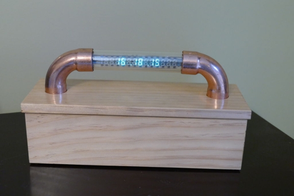
IV-27M Alarm Clock
Project date: March 2019 – May 2019
Overview
After the successful completion of the XIV Nixie Clock which was Direct/Static Driven, I was keen to start work on a new clock which was based on the Multiplexing(Dynamic) or “MUX” principle of operation, known also as “Muxing”. The new clock would be based on the USSR manufactured IV-27V VFD, 13 element, 7 segment tube. This tube requires a 24V common anode DC supply, which dictates what type of IC chip(s) are needed to support the multiplexing operation. To further understand multiplexing the following Wikipedia articles where of great help:
To understand how VFD displays work and what is involved in driving the display using either Direct or Multiplexed driver the following article was very useful:
The clock would have a simple function of displaying Time, Date, Humidity, Temperature, Pressure and an Alarm feature..
Here is a brief summary of how the IV-27M tube works:
The tube is evacuated (vacuum). In the tube is a substrate (anode) (usually based on phosphorus), which begins to shine when “bombarded” with electrons.The electrons come from a heater (cathode), which are in the form of very thin tungsten wires. Between the substrate (anode) and the heater (cathode) a control grid is mounted which is used to turn on and off the individual elements. The tube used here consists of 13 seven-segment displays.
The tube was manufactured in Russia in 1985 and carries the Russian Quality production mark on the rear of the tube. Both tubes I purchased came from an Ebay supplier “nixiestore” who I would highly recommend.
Supplies:
1. Arduino Mega 2560
2. MAX6921AWI Chip
3. TSSOP28 PCB board, 28 pin connection
4. IV-27M Russian 13 grid, 7 segment tube
5. BME280 sensor
6. 3W speaker
7. 16×2 LCD display with IC2 connection board
8. Green LED with 330 ohm resistor
9. RTC clock with battery backup
10. 12V to 3.5V Step Down DC-DC Adapter
11. 12V to 24V Boost DC-DC Adapter
12. 12V, 1A power Adapter
13. Two pole switch
14. 16 key keypad
15. Hot Glue, wood for box, felt feet, clear gloss varnish.
16. 30 AWG multi-coloured wire, heat shrink, PCB female connections.
17. Dupont connection wires
18. Plastic stand-offs for support of components
19. Arduino Board two pin Power Input plug
20. Small PCB board and two sets of header pins
Step 1: Pin Assignment of IV-27M
Cathode Heater Voltage
It is very important to use 3.5V. There have been some references to using 5V on the internet. While this could be used it will over-heat the grid heaters. To see this in operation view the IV-27M tube, while it is working, in a darkened room, the two heater lines can clearly be seen glowing red!
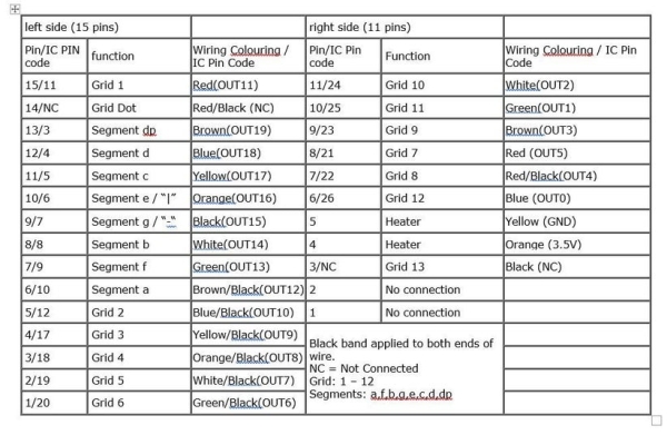
Pin-outs
The first part of the project was to determine the pinouts on the IV-27M tube. There are Russian language-based datasheets and numerous Internet based descriptions of the left and right pinouts. Looking at the tube with the digits facing you, the left hand end has 15 pins and the right hand end has 11 pins. I simply soldered coloured 30 Gauge wires to both ends terminating in Dupont breadboard pins. Six of the left hand wires and one of the right hand wires had black heat shrink bands added to each end in order to differentiate them from the other solid colour wires.
Read more: VFD Alarm Clock
- What is the primary operating principle of this new clock?
The clock is based on the Multiplexing or MUX principle of operation. - Does the IV-27M tube require a specific common anode voltage?
Yes, the tube requires a 24V common anode DC supply. - How should the Cathode Heater Voltage be set?
It is very important to use 3.5V to prevent overheating the grid heaters. - Can 5V be used for the heater voltage?
While it could be used, it will over-heat the grid heaters. - What function does the BME280 sensor serve?
The sensor measures humidity, temperature, and pressure. - How are the pinouts identified on the IV-27M tube?
Looking at the tube with digits facing you, the left end has 15 pins and the right end has 11 pins. - What visual indicator shows the heater lines are glowing?
In a darkened room, the two heater lines can clearly be seen glowing red. - Which supplier is recommended for purchasing the tubes?
The eBay supplier nixiestore is highly recommended.