Summary of Use Arduino to Interface with a Remote Controlled Power Switch
Summary (under 100 words): The author reverse-engineered a cheap 434 MHz remote-controlled power socket set. The remote uses an HT2262 encoder and transmitter; pressing a button feeds VCC to encoder input pins which drives RF transmission. By simulating button presses with Arduino I/O pins wired to the SW1/SW2/SW3 pads, the Arduino can control the sockets. HT2262 accepts 4–18V so Arduino 5V works, though higher voltage increases range. A driver can be added to supply higher voltage for improved transmission distance.
Parts used in the Remote Controlled Power Switch Project:
- Remote controlled switch sockets (one remote + three sockets)
- Remote control PCB with HT2262 encoder
- 434 MHz RF transmitter circuit (on remote)
- Arduino (microcontroller)
- Wires to connect Arduino I/O to SW1, SW2, SW3 pads
- Optional higher-voltage source driver (to drive encoder above 5V)
Update: check out the RFToy — an easy-to-use standalone gadget to control remote power sockets. Also, support for remote power sockets have been added to OpenSprinkler firmware 2.1.1.
For a while I’ve been looking for a way to switch household power line (110V) devices. One of the simplest options is to use a relay that is connected to the power line. This is easy in concept but quite dangerous to work with. You don’t want to accidentally touch the power line wire and shock yourself. A much better option is to use thepowerswitch tail, which insulates the relay and the relevant circuity inside a plastic enclosure, leaving only two MCU pins to interface with. Much safer. But you still have to run wires between your MCU and the power socket. I am more interested in an wireless option.
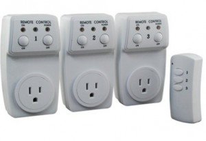
Recently I purchase a set of remote controlled switch sockets from Amazon. It comes with one remote and three sockets, each of which can be individually switched. The whole package is quite cheap. The way this works is that you plug the sockets into the wall, and when you press a button on the remote, the corresponding socket will switch, thus turning on or off the device connected to the socket.
I took apart the remote control and found that the circuit is quite simple. It’s based on an HT2262 remote control encoder and a 434 MHz transmitter circuit. In fact, the schematic of the circuit is well documented in the datasheet of the encoder:
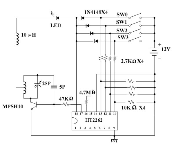
From the schematic, it’s quite clear that when a button is pressed, the input voltage is fed to one of the encoder pins (as well as the VCC pin of the encoder). Then the encoder will send the signal to the RF transmitter circuit. The RF signal will be received at the power socket side and decoded. Very simple. Now, to use my Arduino to interface with this power switch, all I need to do is to simulate a button press by sourcing a positive voltage to wires labeled SW1, SW2, SW3 etc. It turns out that the HT2262 can work with a fairly wide range of voltage: from 4V to 18V. Clearly the 5V output from an Arduino IO pin falls within the acceptable range. So I can simply connect those wires individually with Arduino I/O pins, and write a program that outputs HIGH momentarily when I need to switch a device. The only downside is at 5V the transmitting range is limited. The higher the input voltage, the longer distance it can transmit. So a more flexible design is to have a ‘source’ driver to supply higher than 5V to the encoder.
For more detail: Use Arduino to Interface with a Remote Controlled Power Switch
- How does the remote control switch the sockets?
Pressing a button feeds input voltage to an HT2262 encoder pin which drives a 434 MHz transmitter; the socket receives and decodes the RF signal to switch. - Can an Arduino simulate the remote buttons?
Yes; the Arduino can source 5V to the SW1/SW2/SW3 pads to simulate button presses. - What voltage range does the HT2262 accept?
The HT2262 works with a voltage range from 4V to 18V. - Does using Arduino 5V affect transmission range?
Yes; at 5V the transmitting range is limited compared to using higher input voltage. - What is a safer alternative to wiring a relay to mains?
Using a prebuilt power switch tail that encloses the relay and circuitry in a plastic enclosure is much safer. - Can range be improved without changing the remote PCB?
Yes; adding a source driver to supply higher than 5V to the encoder can increase transmission distance.