Summary of Stupid Simple Arduino LF RFID Tag Spoofer
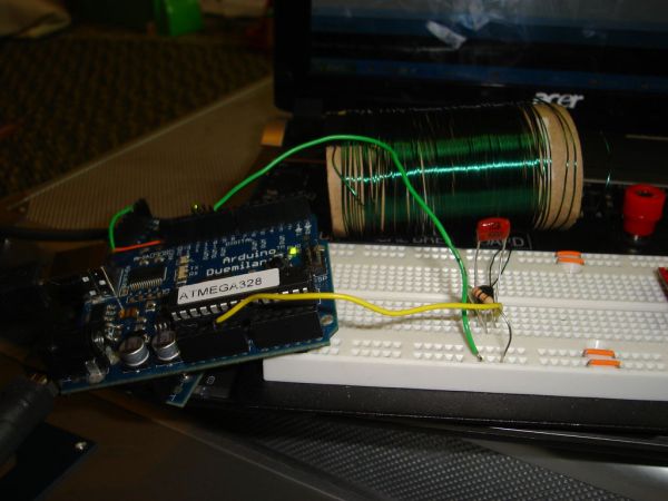
This article demonstrates how to build a simple Arduino-based device that spoofs 125 KHz low-frequency RFID tags using basic components like wire, a transistor, capacitor, and resistor. The project relies on inductive coupling and Manchester encoding to mimic passive tag behavior without specialized hardware.
Parts used in the Stupid Simple Arduino LF RFID Tag Spoofer:
- Enamel coated solid core copper wire
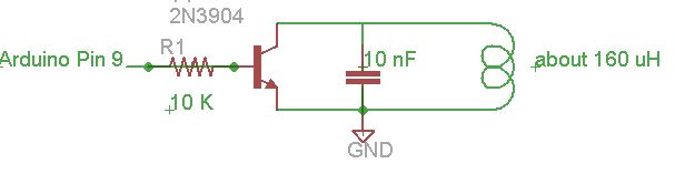
- NPN transistor (2N3904)
- 10 K Ohm Resistor
- 10 nF capacitor (0.01 uF)
- Toilet paper roll
- Arduino
- Parallax RFID serial reader (for testing)
RFID tags are all over the place. They’re used in building access control systems, passports, inventory tracking . . . This instructable will show how you can use an Arduino and a few simple components (wire coil, transistor, capacitor, resistor) to make a device that can spoof an 125 KHz (low frequency) RFID tag. This is version 1, so there are many enhancements that can be made, but this version is stupid simple, yet it works. I did this in a few hours without much previous knowledge of RFID and without any fancy equipment (like a radio tuning hardware or an oscilloscope . . .I guess an oscilloscope is fancy, I need to pick up one of those).
UPDATE: Here is a link to an Arduino Mini shield based on these instructions http://wiki.smallroom.net/doku.php?id=terd:projects:rfidspoofer
Step 1: Parts
*Some enamel coated solid core copper wire (I used the green spool from the 3 spool set Radio Shack carries).
*A NPN transistor, I used a 2N3904
*A 10 K Ohm Resistor
*A 10 nF capacitor (0.01 uF). I’m using a Metalized polyester film cap I got from Radio Shack, others should work though
*A toilet paper roll to wind the wire on
I tested my circuit using a Parallax RFID serial reader connected to a second Arduino
Step 2: RFID background
A passive RFID tag has a coil and a chip with data on it. An RFID reader has a coil in it that has a coil in it that creates a varying electronic field (in this case 125 KHz), which is called the carrier signal. When the tag is close to the RFID reader then the magnetic field powers the chip on the tag, which then responds by tuning and detuning its own antenna. This all works on the principle of inductive coupling, to learn more about his see www.rfid-handbook.de/rfid/types_of_rfid.html
125 KHz cards use manchester encoding to encode the data to send it to the reader. Manchester encoding basically takes the XOR of the bit that needs to be transmitted and the clock value. So if the clock value is low (0) and the value to transmit is 1 then it would be 0 XOR 1 which is 1. This has to be done on every clock cycle. For more information on manchester encoding see en.wikipedia.org/wiki/Manchester_code.
Step 3: The Data
you can either download the code below, or get it here: www.scribd.com/doc/30215336/RFID-Faker-Code
The serial number of a tag is sent over using a fairly simple protocol.
The serial number of a tag is sent over using a fairly simple protocol.
For more detail: Stupid Simple Arduino LF RFID Tag Spoofer
- What frequency do the RFID tags operate at?
The tags operate at 125 KHz. - How does a passive RFID tag get powered?
The magnetic field from the reader powers the chip on the tag through inductive coupling. - Which encoding method is used for 125 KHz cards?
Manchester encoding is used to encode the data sent to the reader. - Can this project be built without an oscilloscope?
Yes, the author completed the project without fancy equipment like an oscilloscope or radio tuning hardware. - What type of transistor is recommended for this circuit?
A NPN transistor, specifically the 2N3904, is used. - How can I download the code for this project?
The code can be downloaded directly from the text or found at www.scribd.com/doc/30215336/RFID-Faker-Code. - What component is used as the form to wind the wire coil?
A toilet paper roll is used to wind the enamel coated solid core copper wire. - How was the circuit tested by the author?
The circuit was tested using a Parallax RFID serial reader connected to a second Arduino.