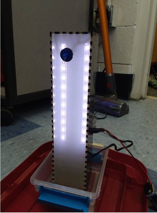
For our SIDE project, a year long project that we do for Ms. Berbawy’s Principles of Engineering class, we decided to make a stroboscopic fountain. The stroboscopic effect, pioneered by Harold Edgerton, makes objects appear as though they are moving in slow motion. How does this work? A strobe light is flashed at the same rate and time as an object is moving. Every time the strobe light flashes, it illuminates the object in the object in the position that it is in. In the case of the fountain, the strobe light flashes every time the water droplets are in the same position relative to the lights, so it looks as though the water droplets aren’t moving when they are actually getting replaced by the water droplet after it each time the strobe light flashes, you just can’t see it. We based our build off of Joli Factory’s Instructable, including buying their circuit board kit and using their sketch.
WARNING: this project uses a strobe light, which may be harmful to people sensitive to flashing lights
Materials Needed:
- Joli Factory PCB electronics kit
- Solder
- Arduino Nano
- 0.125″ extruded acrylic (black and clear/frosted clear)
- Black: 667.15 cm squared
- Clear: 370.5 cm squared
- Acrylic cement or gel
- (4) M2x10 screws
- (4) M2 nuts
- Single color LED strip
- Stranded wire (2 colors optional)
- Foam core board
- VicTsing 80 GPH Submersible Water Pump
- (1) 2 gph drip irrigation emitter
- (1) 12″ lenght of 0.25″ irrigation tubing
- (1) battery clip with male DC plug
- (1) 9V battery
- Small container
Tools Needed:
- Soldering iron
- Scissors
- Exacto knife
- ULS 3.5 40W laser cutter
- 636-080-AC-HD screwdriver
- Syringe and applicator if using acrylic cement
- Wire stripper
- Needle nose pliers
- Flash drive
- Butcher paper
- Gloves and safety goggles
- Scotch tape
- Tacky glue
- USB A to B cable
Step 1: Building the PCB
The kit sold by Joli Factory on their Tindie store includes
- 1 x PCB
- 1 x power socket
- 1 x push button switch
- 1 x 3300uF 16V electrolytic capacitor
- 3 x 12K ohms 1/4 W resistor
- 3 x 330 ohms 1/4 W resistor
- 3 x IN4004 diode
- 3 x N-Channel MOSFET 60V 30A
- 3 x 50K ohms potentiometer
- 2 x 15 pin straight female header
Using a soldering iron, solder the parts according to the diagram provided in the pictures.
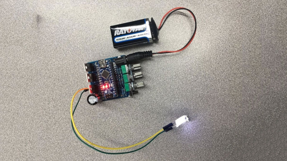
After everything is soldered onto the board, fit the Arduino nano into the pin headers with the USB port facing the side away from the capacitor.
We also used the sketch provided by Joli Factory and downloaded the PWM library needed for the code to work. Using a USB B to A cable, we uploaded the project into the Arduino nano and made sure that it worked by plugging the battery into it. The light on top of the board should be red. If there is a flashing light, your Arduino may have the preset “blinking” code on it, which you can either delete or just replace with the fountain code. We also connected an LED to the board using two jumper wires to test it, but this is optional.
Step 2: Casing and Main Panel
In order to make the main casing of the fountain, we used Maker Case, which automatically adds fingers to the vector file so that once it’s cut out, the box will have more stability. Make a box with the dimensions 71mm x 300mm x 65mm, as provided by Joli Factory’s tutorial, and add 3mm fingers then download the vector file into Adobe Illustrator. In Adobe Illustrator, delete the bottom panel, since we don’t need it for the fountain. Then, following the dimensions and specifications seen in the PDFs of the panels, add the holes for the potentiometers, battery socket, and push button in the right panel, a 0.25″ hole in the front panel for the tube, and add a slot in the back panel, which is where the wire for the pump will go. All of the lines are then made solid red with 0.01 pt stroke so that the laser cutter can pick it up. The back, left, right, and top panels are then moved to a separate file, since they are in a different color.
In the same file as the front panel, follow the diagram with the dimensions and specifications to make the main panel, which will go inside the casing. The four small holes in the middle (all are the same dimensions) will be used to attach the PCB, the larger hole in the top will be used to feed the tube through to the front panel, and the slot at the bottom is for the tubing and wiring. Make all of the lines solid red and 0.01 stroke, save as an ai file onto the flash drive, and upload onto the laser cutter set to extruded acrylic with 0% change, and cut out the main panel from clear acrylic.
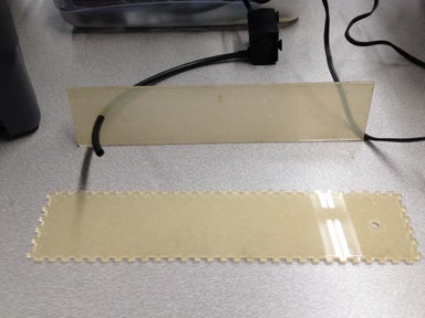
The two files are then saved as .ai files and saved onto a flash drive, then uploaded into the laser cutter to be cut. Set the laser cutter to extruded acrylic with 0% changing laser, then cut out the back, left, right, and top panel file out of black and the front and main panel out of clear. Do not remove the protective film on the clear acrylic for the front panel. Make sure that all of the panels fit together and will accommodate the components before continuing further. In the pictures, the left panel has smudges from a previous attempt to glue the pieces together; there should be nothing done to the panels at this point.
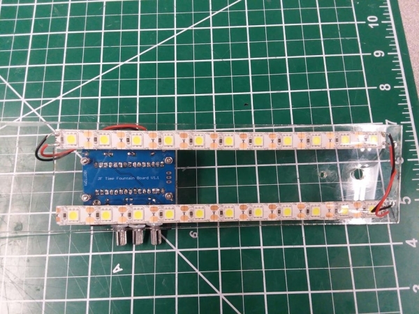
Step 3: LED Strips
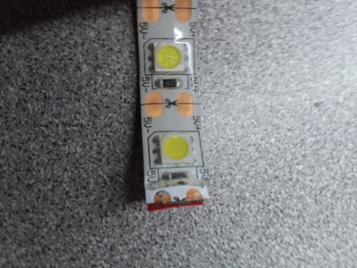
From the roll of LEDs, cut out two sections with 11 LEDs per, making sure to cut in the middle of the copper plates. Then, use the exacto knife to cut off the gel layer on the ends so that the copper is exposed. Make sure to not disturb any other part of the strip or damage the copper plates. Cut out four 3.5″ lengths of stranded wire and use the wire strippers to remove at least 0.25″ of the insulation on all ends. Though not necessary, two of our wire sections are red and two are black so that it’s easier to distinguish.
Using the soldering iron, solder two of the wires to the tops of the LED strip sections. In the picture, the red wire connects the positive copper plates and the black wire connects the negatives. On the left LED strip, solder the remaining two wires to the bottom, connecting it to the PCB at the ports in front of the mosFET closest to the capacitor, making sure that the positive and negative ends line up. Again, in the pictures, red is positive and black is negative. The PCB has the positive and negative end labeled, so it it easy to tell. Plug in the battery to make sure that the LED strip works and is properly soldered.
Step 4: Main Panel
Using the screwdriver and needle nose pliers, attach the PCB to the main panel with the screws and nuts. Make sure that the top of the PCB (the side with the Arduino) is facing away from the main panel and the edge of the PCB with the potentiometers is facing away from the slot in the main panel. The included pictures of attaching the PCB were taken before the LEDs were soldered on (the PCB had to be taken off to solder on the LEDs and reattached later), but the positioning is still the same. Feed the wires attaching the PCB to the LED strip through the slot so they don’t get pressed against the side of the panel later, then remove the protective backing on the LED strips and stick them to the front of the main panel about 0.5″ from the top (the side the PCB is not on) so that the LEDs span both sides of the panel.
Step 5: Assembling the Casing
Fit the back, left, right, and top panels together. When assembled, the back panel slot should be on the right side while facing the front of the fountain. The right panel should have the push button hole at the top and the power socket hole at the bottom, with the whole line of holes closer to the back than the front. The fingers should help it hold together by itself, but we secured it with scotch tape so it wouldn’t move while using the acrylic cement.
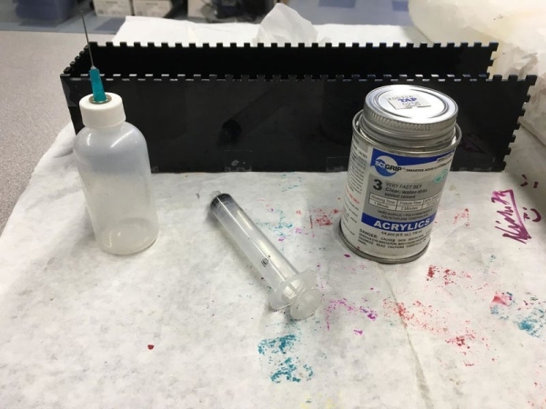
Line your work surface with butcher paper to protect it, then put on the gloves and safety goggles. Using the syringe, intake a small amount of the acrylic cement from the canister. Immediately recap the canister, as acrylic cement vaporizes quickly. Expel the acrylic cement into the applicator, cap the applicator, hold the applicator upright, and squeeze all of the air out so that the acrylic cement doesn’t leak out while in use. Holding the applicator upside down, squeeze lightly to apply the acrylic cement to the intersections. Put the casing to the side and wait for the acrylic cement to fully dry.
Source: Stroboscopic Fountain