
Summary of The Soil Temperature Sensor using arduino
This project builds a waterproof soil temperature sensor using an LM335 temperature sensor enclosed in glue-lined heat-shrink tubing, with optional calibration resistors, soldered lead wires, and a local connection to the system ground and signal. The resistor(s) on the ADJ leg allow calibration of individual LM335 units; wiring can be done inline for simplicity. The assembly is buried in soil and connected back to the controller for temperature measurement.
Parts used in the Soil Temperature Sensor:
- LM335 temperature sensor
- 33K resistor
- 56K resistor
- Glue-lined heat-shrink tubing (short piece)
- Soldering iron and solder
- Lead wires
You are building a soil temperature sensor. We need a waterproof thermometer that we can burry in the soil. The sensor is made up of a small circuit enclosed in a piece of heat shrink (to waterproof it).
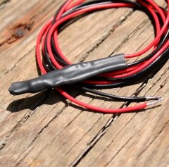
(see the parts page)
- an LM335 temperature sensor
- a 33K and a 56K resistor
- a short piece of glue-lined heat-shrink tubing
- soldering iron and solder
- lead wires
The circuit for the actual sensor
This is the circuit for our waterproof sensor (not to be confused with the local circuit below).
The resistor in this circuit is optional. You can just get the value of the LM335 raw and use it in calculations (see below). But if we want to know the actual temperature we will need to use a resistor to calibrate the sensor.
If you do want to use a resistor, you can make things simpler to wire up in the garden by soldering the resistor(s) inline with this sensor. See more detailed info below to see why this is technically not correct. This resistor is to calibrate the LM335 temperature sensor. The actual value of the resistor will vary from unit to unit. You will need to calibrate it by trying different resistors.
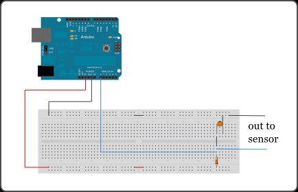 The ground leg will be tied to the common ground connection with your other sensors. The output leg will need a signal wire to get back to the brain where it will be connected to the local circuit for this module.
Step-By-Step
Attach the two resistors to the ADJ leg of the LM335. Attach a piece of lead wire to the positive leg that will reach to the end of the ADJ leg.
For more detail: The Soil Temperature Sensor
- What sensor is used for the waterproof soil thermometer?
The LM335 temperature sensor is used. - How is the sensor waterproofed for burying?
The small circuit is enclosed in a piece of glue-lined heat-shrink tubing to waterproof it. - Are resistors required in the circuit?
The resistor is optional; you can use the LM335 raw, but a resistor is used to calibrate the sensor if desired. - Which resistors are suggested for calibration?
A 33K and a 56K resistor are listed as supplies for calibration. - Where are the resistors attached on the LM335?
The resistors are attached to the ADJ leg of the LM335. - How is the sensor connected to the rest of the system?
The ground leg ties to the common ground and the output leg uses a signal wire back to the brain/local circuit. - Can resistors be soldered inline for garden wiring?
Yes, resistors can be soldered inline to simplify wiring, though the article notes this is not technically correct. - How do you determine the correct resistor value for calibration?
The actual resistor value varies unit to unit and must be found by calibrating and trying different resistors.
