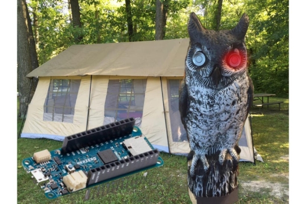
This Instructable is to build a very smart, talking campsite security system that is disguised in an owl decoy. Now, this isn’t your typical Arduino ultrasonic distance sensing project. Rather, you will learn how to reverse engineer the very inexpensive, but far superior automotive bumper backup sensors for very wide beams of detection. You’ll also learn how to build a small amplifier for audio applications.
This security alarm can also be set on one’s porch. I designed it against the following requirements:
- doesn’t have to wait until a door is kicked in or a window is broken to trigger an alarm to spook away the intruder
- automatically talks to the intruder to threaten calling the police
- has a wide beam that can’t be evaded
- sends a notification to your cell phone when it detects intrusion
Supplies
- Parking Sensor Kit
- ESP8266 (Optional for cell phone notification)
- Arduino MKR Zero
- DIY Amp (Optional):
- LM386
- 8 ohm 1/2 Watt Speaker
- 10 ohm resistor
- (2) 4.7K resistors
- 10uF Capacitors
- 0.1uF Capacitor
- 220 uF Capacitor
- Or a great purchased amp:
- An Owl Decoy
- Tools:
Digital Multimeter
Logic Analyzer (Optional) - Code and the Owl Base 3D File:
Step 1: Learn the Features of the Arduino MKR Zero
The Arduino MKR Zero is my pick of the litter for this build. Here is why:
- ~$25 US dollars
- 10 Bit DAC
- allows us to play sound files on demand
- SD Card Slot
- allows us to load up dozens of custom sound and voice sounds
- 22 Digital Pins, SPI, and I2C
- allows us to tap into the automotive bumper backup sensor brains with plenty of pins for expansion of other sensors
- Built in Battery Charge Management and connection
- allows us to go cable free if desired – allows us to secure a campsite, too!
The only thing it is missing is WiFi. So, we designed in a ESP8266 to handle sending a message to your cell phone.
Step 2: Learn How Automotive Backup Sensors Work

Car parking sensors use ultrasound, which is an acoustic wave with a very high frequency. The frequency is beyond human hearing above 20kHz. What is amazing about it is how “loud” it is. It sends out a inaudible scream at over 100dB – “louder” than a motorcycle, but does not cause human ear damage.
With that short wave length, it has a good shaped beam which allows for reliable measurements for sensing objects. Also, since it is sound travelling through air, it travels nominally at 340m/s. That’s slow in the world of electrons, so, inexpensive devices can measure the time it takes to “bounce back” easily.
Step 3: Reverse Engineer the Sensor Communication Protocol
If you bought the exact same backup sensor kit as I linked in the description, you can skip this entire step. However, if you didn’t or you want to know how to hack hardware – read on!
To hack the backup sensor, we simply need to figure out how the brain box is communicating to its LED monitor that comes with it. Since different manufactures make these with their own custom protocols, you have to snoop the cables for a communication protocol as well as locate the ground and voltage pins. Here are the substeps to hack it:
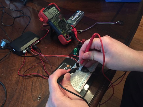
1) Apply a Breadboard to help with probing the circuit:
With the bare eye, you can see that there are four (4) wires going to the sensor kit display monitor. With jumpers, add a breadboard in between the brain box and monitor so we can safely probe without accidentally shorting pins and frying the circuit boards.
2) Find the ground going to the display monitor:
Since it’s automobile tech, the brain box has a 12V nominal voltage source to power it. Based on experience with displays for microcontrollers, it’s more than likely the monitor is powered by no more than 5V.
To start, look for continuity to ground. Set the ohmmeter to beep if you have continuity as it is expected to have zero resistance to ground from the monitor’s ground pin. Touch each wire that connects to the monitor to the ground pin of the brain box until you get a beep. Once you do, you found the ground.
3) Find the Voltage wire:
Now, let’s find the voltage wire. You’ll use it to power the Arduino. That must power the monitor and it will be used to power your Arduino. Hookup a 9V battery to power the module’s power and ground to power it. Now, when you probe the wires, two will fluctuate and one is a solid 5V. That’s the voltage wire. Two down, two to go.
4) Find the Buzzer Wire:
Now, one thing that is going on after you applied the 9V battery is a bunch of beeping from the monitor. The out-of-the-box system is designed to do this to alert the vehicle driver to things getting close. So, on the two remaining wires to snoop, lift one jumper on your breadboard and then the other. The beeping stopped on one of them. That’s the Buzzer wire! We could use it as our trigger and stop here – but let’s keep hacking so we’ll be able to use up to 4 sensors and know which one is triggered.
5) Find the communications wire:
You guessed it. It’s the last one remaining!
If we can tap that, we can do anything we want with proximity data versus just triggering off the beeper wire. We can trigger or suppress at set distances by any of the four sensors. This allows us to adjust our sensors to their environment so we don’t get immediate false triggers. (That makes you smart.)
6) Hack the communications protocol:
With just one wire left, you can rule out the I2C and SPI communication protocols. They require another signal that sets the beat to coordinate the “morse code” of their protocols. Serial communication could be an option here because it is a “fire and forget” protocol at a set beat. It also could be some custom pulse width modulation (PWM) protocol the manufacturer designed.
This is a good time for an oscilloscope or even better, a cheap logic analyzer. You can get them under $15 bucks and they are easier to use than an oscilloscope.
Often, serial communication has a long pulse, which we do have here as you see in the pictures above. After the long pulse, it is followed by 8 segments that may be high or low. The width between each segment is fixed. By measuring the shortest high pulse, I can assume that is the period – and in turn, the corresponding baud rate. A signal analyzer will do all this for you. Or if you have an O-scope, you can move your cursors around to get the measurements.
In this case it does correspond to 9600 baud, which seems plausible for serial communication. But, what doesn’t seem plausible is that we have way more than 8 segments here. In fact, after the long pulse, the count of the beat is not evenly divisible by eight (8). This tells me they have made their own “morse code” messaging system using Pulse Width Modulation on 5Vs.
So, we’ll have to experiment to figure it out. Plugged one ultrasonic sensor into one port at a time. It appears the data is segmented after a very long pulse. (By long, I mean compared to the other pulses.) You can see there are 4 bytes of pulses here as pictured above – a byte representing each sensor port. Short pulses are zero and long pulses are a 1. When the sensor is plugged in, the start of the byte turns to 000 instead of 111. Eureka! Reverse Engineered!
Hacking Results:
We’ve cracked the code: the communication protocol is as follows:
- 1 very long start pulse (code will wait for a pulse this long before calling the parse routine)
- 1 short start pulse (throw away bit)
- short pulses mean zero in each period, long pulses mean one
- 4 bytes worth pulsed out for each packet, each representing a sensors data in order of Sensor A, D, C, B
- If first 3 bits are a zero in the byte, the sensor is recognized.
- Last 5 bytes are binary for decimeters of distance from the given sensor
Step 4: Build the Alarm Sound System (Optional)
If you bought the great, but super cheap, amp from Adafruit listed in the supply section, you can skip making yoru own and just jumper the amp, sensor brainbox, and ESP8266 to the Arduino. If you want to know how to make your own amp, read on! Here are the substeps:
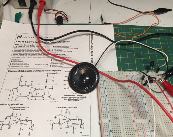
- Get the datasheet for the LM386 amp chip.
- Review the schematic in the pictures above. This circuit combines the amp, Arduino, and Backup Sensor Brain Box – which is the complete assembly of our electronics scope.
- Breadboard the circuit based on the schematic and test it with a music player with a 3.5MM jack.
- Note – the ground of the music player connects to pin 2 of the LM386. This pin is not connected to the ground of the circuit or you will get nothing but noise! This is not intuitive from the datasheet.
- Once you are pleased with your sound on your breadboard, solder the circuit on a protoboard. Refer to the pictures for my board layout.
If you’d like to modify my circuit design, you can get my Eagle Files here.
Step 5: Code the Microcontrollers
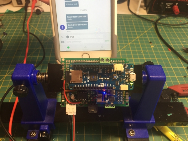
The picture above shows me testing the electronics including the optional cell phone notification. If you bought the car alarm kit I linked in the supplies section, you’ll be able to use this code unmodified. Otherwise, you will need to adjust the Arduino “Sensor” method based on your reverse engineering in Step 2.
This Instructable is based on you being familiar with uploading code to an Arduino. If not, the best place to learn that is at arduino.cc. Follow the normal routine to upload.
For the sound files, just record yourself and save the file to an SD card named alarm.wav and owlHello.wav.
You can get this code on my GitHub as well.
Arduino MKR Zero Code:
#include <SD.h>
#include <SPI.h>
#include <AudioZero.h>

int sense_pin = 0;
int alarm_pin = 1;

unsigned long pulse_length;
unsigned long first_pulse;
int sensorValue[32];
unsigned long lengths[32];
int pulse_value;
float A, B, C, D;
float averageDistance, lastAverage;
int first_few_counter=0;

void setup()
{
  Serial.begin(115200);
  delay(1000);
  A=0;B=0;C=0;D=0;
  averageDistance=0;lastAverage;
  pinMode(sense_pin,INPUT);
  pinMode(alarm_pin,OUTPUT);
  digitalWrite(alarm_pin,HIGH); // Leave it high and pull it low to alarm.
  digitalWrite(A0,HIGH); //kills noise on the line;
  if (!SD.begin(SDCARD_SS_PIN)) {
    Serial.println(" failed!");
    while(true);
  }

  Serial.println("Starting...");
  delay(1000);
  PlaySound("owlHello.wav");
}

void loop() {
  Sense();
  delay(2000);
}

void Sense()
{  Serial.println("Sensing...");
  delay(1000);
  int i;
  //look for starter pulse
  pulse_length = pulseIn(sense_pin, HIGH);

  // wait for the long pulse to signify the start
  while (pulse_length < 1900) {
    pulse_length = pulseIn(sense_pin, HIGH);
  }
  first_pulse=pulse_length;

  // consume the throw away bit
  pulse_length = pulseIn(sense_pin, HIGH);

  // Get the 32 bits to follow
  for (i = 0; i < 32; i ++) {
    pulse_length = pulseIn(sense_pin, HIGH);

    if (pulse_length < 180) {
      pulse_value = 0;
    }
    else {
      if (pulse_length > 1000) {
        Serial.println("Overran!");
        delay(1000);
        return; // just exit out of the routine if it fails to sense correctly this time through.
      }
      pulse_value = 1;
    }
    sensorValue[i] = pulse_value;
    lengths[i]=pulse_length;
  }

  // Sensor A
  if (sensorValue[0]==0) {
    //String sensorA=String(sensorValue[3])+String(sensorValue[4])+String(sensorValue[5])+String(sensorValue[6])+String(sensorValue[7]);
    //Serial.println(sensorA);
    A=16*sensorValue[3] + 8*sensorValue[4] + 4*sensorValue[5] + 2*sensorValue[6] + sensorValue[7];
    A=A/(10*.3048); // convert decimeters to feet
    Serial.println(A);
  }

  // Sensor D
  if (sensorValue[8]==0) {
    D=16*sensorValue[11] + 8*sensorValue[12] + 4*sensorValue[13] + 2*sensorValue[14] + sensorValue[15];
    D=D/(10*.3048); // convert decimeters to feet
    Serial.println(D);
  }

  // Sensor C
  if (sensorValue[16]==0) {
    C=16*sensorValue[19] + 8*sensorValue[20] + 4*sensorValue[21] + 2*sensorValue[22] + sensorValue[23];
    C=C/(10*.3048); // convert decimeters to feet
    Serial.println(C);
  }

  // Sensor B
  if (sensorValue[24]==0) {
    B=16*sensorValue[27] + 8*sensorValue[28] + 4*sensorValue[29] + 2*sensorValue[30] + sensorValue[31];
    B=B/(10*.3048); // convert decimeters to feet
    Serial.println(B);
  }
  averageDistance=(A+B+C+D)/4;
  if (((abs(lastAverage-averageDistance))/lastAverage)>.1) alarm();
  lastAverage=averageDistance;
}
void alarm(){
  if (first_few_counter++<3) return; // this keeps it from triggering when you first set it down and turn it on.
  digitalWrite(alarm_pin,LOW);
  PlaySound("alarm.wav");
  delay(5000);
  digitalWrite(alarm_pin,HIGH);
}

void PlaySound(String the_sound)
{
  File myFile;

  // open wave file from sdcard
  myFile = SD.open(the_sound);

  // until the file is not finished
  AudioZero.begin(44100);
  AudioZero.play(myFile);
  myFile.close();
  AudioZero.end();
  digitalWrite(A0,HIGH); //kills noise on the line;
}
Optional: For communicating with my phone, I use Pushbullet for the messaging system. You will need to establish a key and replace “YOURPUSHBULLETKEY” with it.
ESP8266 Code:
#include <ESP8266WiFi.h>
#include <WiFiClientSecure.h>
const char* ssid = "YOURSSID";
const char* password = "YOURPASSWORD";
const char* host = "api.pushbullet.com";
const int httpsPort = 443;
const char* PushBulletAPIKEY = "YOURPUSHBULLETKEY"; //get it from your pushbullet account
// Use web browser to view and copy SHA1 fingerprint of the certificate.  Click the lock by the address in the browser and then click view certificate.
// Alternately, go to <a href="https://www.grc.com/fingerprints.htm"> <a href="https://www.grc.com/fingerprints.htm" rel="nofollow">  https://www.grc.com/fingerprints.htm  </a> </a> and enter api.pushbullet.com
const char* fingerprint = "BB FC 9F 1B C1 3C D9 96 F2 68 A2 E3 41 29 D1 47 8F B9 33 BE";
void setup() {
  Serial.begin(115200);
  Serial.println();
  Serial.print("connecting to ");
  Serial.println(ssid);
  WiFi.mode(WIFI_STA);
  WiFi.begin(ssid, password);
  while (WiFi.status() != WL_CONNECTED) {
    delay(500);
    Serial.print(".");
  }
  Serial.println("");
  Serial.println("WiFi connected");
  Serial.println("IP address: ");
  Serial.println(WiFi.localIP());
  pushBullet("The Owl Orb of Protection Has Started!");
  pinMode(2,INPUT_PULLUP);
}
void pushBullet(String the_msg){
      // Use WiFiClientSecure class to create TLS connection
      WiFiClientSecure client;
      Serial.print("connecting to ");
      Serial.println(host);
      if (!client.connect(host, httpsPort)) {
        Serial.println("connection failed");
        return;
      }

      if (client.verify(fingerprint, host)) {
        Serial.println("certificate matches");
      } else {
        Serial.println("certificate doesn't match");
      }
      String url = "/v2/pushes";
      String messagebody = "{\"type\": \"note\", \"title\": \"ESP8266\", \"body\": \""+the_msg+"\"}\r\n";
      Serial.print("requesting URL: ");
      Serial.println(url);

      client.print(String("POST ") + url + " HTTP/1.1\r\n" +
                   "Host: " + host + "\r\n" +
                   "Authorization: Bearer " + PushBulletAPIKEY + "\r\n" +
                   "Content-Type: application/json\r\n" +
                   "Content-Length: " +
                   String(messagebody.length()) + "\r\n\r\n");
      client.print(messagebody);

      Serial.println("request sent");

      //print the response

      while (client.available() == 0);

      while (client.available()) {
        String line = client.readStringUntil('\n');
        Serial.println(line);
      }
}
void loop() {
  delay(200);
  if (digitalRead(2)==LOW) {//Wait for pin 2 to go to ground to trigger.
    pushBullet("The Owl has detected something!");
    delay(5000);
  }
Source: Reverse Engineered Bumper Sensor Campsite Security Alarm