Summary of Remote Smoke Alarm Buzzer & Microcontroller Interface
This project modifies escape-light smoke alarms to trigger a remote buzzer, extending alerts to distant areas like garages. It includes building a buzzer module and an optional microcontroller interface for monitoring or additional triggers. The system allows multiple alarms to share a single remote buzzer via a two-core cable. Crucially, the modified alarm serves as an auxiliary alert and should never replace standard safety devices.
Parts used in the Remote Smoke Alarm Buzzer:
- New Smoke Alarm with Escape Light (two 9-volt batteries)
- PNP 800mA Transistor (e.g., BC327 or equivalent)
- Resistors: 15Ω, 10kΩ, 82Ω, 820Ω
- Red LED 3mm
- Pair of Female & Male connectors (2 pin polarised, e.g., JST)
- Red/black cable (current rating < 1amp)
- Heat shrink sleeving
- Active Buzzer 5 Volt
- Housing (e.g., Easy Measure cereal cup or small project box)
Add a remote buzzer to Smoke Alarms that are too far away be heard. Also add an optional Microcontroller interface e.g. Arduino.
This document describes how to:
- Modify an escape-light type smoke alarm to sound a remote buzzer
- Create the buzzer module
- Create a microcontroller alarm interface including PCB layout
- Use an Arduino code example to monitor the alarms and sound the buzzer
Features:
- Alert occupant to an alarm that’s triggered in a distant room/garage/attic
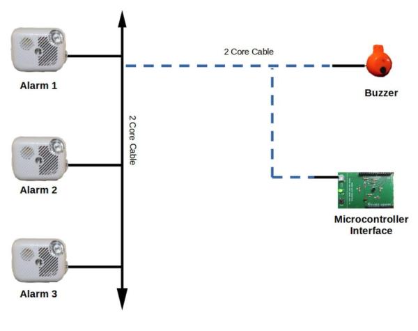
- Allow multiple smoke alarms and buzzers to be connected together with a two core cable.
- Monitor smoke alarms from a microcontroller (e.g. it could send a text if the house is unoccupied)
- Activate the buzzer from the microcontroller (it may be monitoring e.g. water tank level)
*Important Note*
The modified smoke alarms should be used in addition to the existing smoke alarm(s) as you cannot rely on a modified alarm in the case of a fire!
Supplies:
- New Smoke Alarm with Escape Light (has two 9-volt batteries)
- PNP 800mA Transistor e.g. BC327 or equivalent
- Resistors: 15Ω, 10kΩ, 82Ω, 820Ω
- Red LED 3mm
- Pair of Female & Male connectors, 2 pin polarised, e.g. 2 pin micro JST, with wire cables.
- Red/black cable – length from remote smoke alarm to buzzer, e.g. bell wire. Current rating < 1amp
- Heat shrink sleeving
- Active Buzzer 5 Volt.
- Housing for the Buzzer module: “Easy Measure” cerial pcoop or a small project box
Step 1: Obtain a Smoke Alarm/Detector With Escape Light Feature
Before you Start
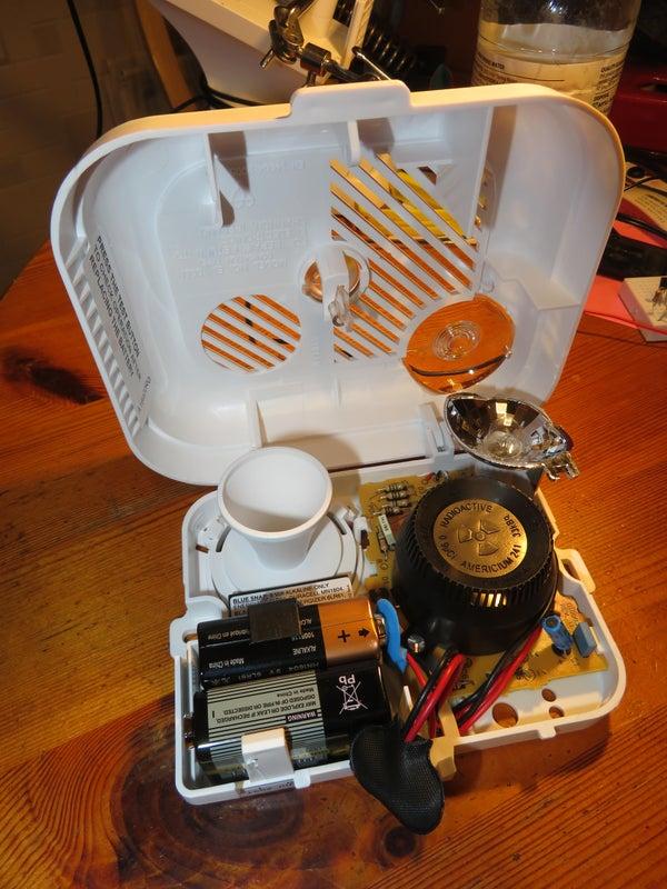
There are two 9 volt PP3 batteries in smoke alarms with an ‘Escape Light’ feature. We need to find the battery that powers escape light, it may be marked in the alarm but if not follow this procedure:
Disconnect one of the two batteries in the smoke alarm and press the smoke alarm’s test button. If the alarm sounds then that battery & connector is powering the smoke alarm and the other connector (the one we are looking for) powers the light. If the alarm doesn’t sound then swap connectors and try again. Make a note of which battery connector powers the escape light.
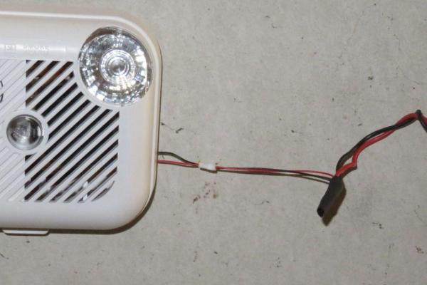
The photos show two different smoke alarms, the on on the left has an LED escape light, the other a filiament bulb. Either will work with the modification descibed here.
Step 2: Identify & Mark the Connections in the Smoke Alrm
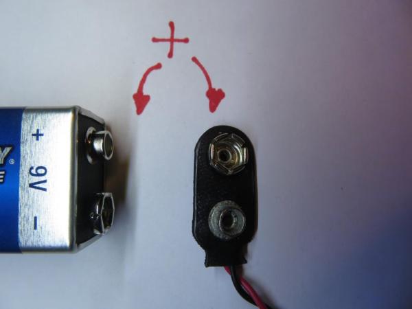
Remove both batteries and proceed to check the lamp battery connector with a multimeter set to continuity beep.
Determine if the +ve (positive) terminal on the battery connector is connected to one of the lamp connections. Mark this connection as #1 e.g with a sticky note. Then the other lamp connector is marked #2.
Using the multimeter find where the -ve (negative) battery connecor goes in the alarm board. Mark it #4.
To Summarise:
- Connection #1 is the +9 volt terminal from the battery to the Lamp/LED
- Connection #2 is the other lamp connection
- Connection #4 is the negative terminal from the battery
See these connections marked with sticky notes in the photo. These connection numbers match those in the circuit diagram.
Note: if instead you discover that the positive battery connection is not connected to any part of the lamp and instead it’s the negative battery terminal connected to the lamp then you will need a different circuit diagram than the one shown – in this case see the expanded project instructions at: tek4um.com/smokeAlarm
Step 3: Solder Transistor With Resistors and Wires
Solder on the wires & resistors for the BC237 PNP transistor as in the photo.
- Collector, red wire. No resistor.
- Base, yellow wire in series with R9 10kΩ resistor
- Emitter, red wire in series with R10 15Ω resistor
Cover solder joints and resistors with heat shrink sleeving.
Step 4: Connect the Wired Transistor to the Alarm
In the Alarm solder the following:
- Collector C to the Lamp battery +9 volt circuit, #1
- Base B (after resistor) to #2 -ve Lamp/LED
- Emitter E (after resistor) to red on the JST connector male Red wire, #3
- Output female JST connector male black wire, #4, to the -ve of the battery (lamp battery)
The last two photos are a different alarm to show an alternative example of the connections. It is a type with a bulb, which was temporarly removed to do the wiring. The left-most bulb connector was found to be connected to the +9volt battery, red lead transistor emitter (#1). The righ-most bulb connector is then connected to the yellow transistor base wire (#2). The last transistor collector wire red goes to the red JST connecor wire (#3). The black JST wire goes to the battery negative which, using the multimeter, was found to be the resistor lead on the alarm PCB that you see in the last photo (#4).
Step 5: Construct the Buzzer Module
The Buzzer module is fitted inside a ‘easy scoop’ cereal cup, but any similar enclosure or small project box will do.
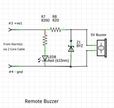
Solder the components according to the buzzer module circuit diagram referring also to the photos.
The 5volt active buzzer has +positive & -negative terminals, they will be marked, or if not check for ‘+’ on the sticker it came with.
Note the zener diode polarity, the cathode (black stripe) goes to the +ve on the buzzer.
Solder the male JST cable, connecting the red to #3 and black to #4 (the photo shows a 3 pin JST connector – a 2 pin is all that is required)
You can test your buzzer when finished by connecting the #3 to + on a 9 volt battery and #4 to the battery negative.
Fit the two batteries to the alarm and using ear muffs….
Connect the buzzer to the modified alarm with the JST connectcors. Press the test button, it will sound, it’s light will come on and the connected buzzer will sound and it’s LED will light.
Step 6: Connecting Up the Alarms & Buzzer
Run a two core cable form the alarm to the buzzer module.
This could be doorbell or house alarm type cable, ideally use a red/black coloured cable to ensure the the polarity is correct.
Fit JST connectors to the cable at either end.
Source: Remote Smoke Alarm Buzzer & Microcontroller Interface
- How do I identify which battery powers the escape light?
Disconnect one battery and press the test button; if the alarm sounds, that battery powers the alarm, so the other connector powers the light. - Can I connect multiple smoke alarms to one buzzer?
Yes, you can connect multiple smoke alarms and buzzers together using a two core cable. - What is the best way to ensure correct polarity when running cables?
Use red and black colored cable, such as doorbell or house alarm type cable, to ensure polarity is correct. - Does the project include a microcontroller interface?
Yes, the document describes creating a microcontroller alarm interface including PCB layout and provides an Arduino code example. - What components are needed for the transistor circuit?
You need a PNP 800mA Transistor, a 10kΩ resistor for the base, and a 15Ω resistor for the emitter. - How do I verify the connections on the smoke alarm board?
Use a multimeter set to continuity beep to find where the negative battery terminal connects and mark the positive lamp connection. - Is it safe to rely solely on this modified alarm?
No, the modified alarms should be used in addition to existing smoke alarms because you cannot rely on a modified alarm in case of a fire. - What housing options are available for the buzzer module?
You can use an Easy Measure cereal cup or any similar enclosure or small project box.