Summary of Remote Control: Interacting with an Arduino via Web Interface
Summary: This tutorial shows how to control a blue LED on an Arduino using a W5100 Ethernet shield and a simple web page. It covers connecting the shield, wiring an LED to pin 2 with a 10K resistor, uploading example Arduino code to host a web server at a fixed IP, and sending URI commands to turn the LED on and off via a browser.
Parts used in the Arduino Ethernet LED Web Control:
- Arduino UNO or Arduino Mega 2560
- W5100 Ethernet Shield (Sunfounder clone)
- Blue LED
- 10K Ohm Resistor
- Ethernet cable
- USB cable (for PC connection and power)
Upon acquiring my initial Arduino board, my immediate aspiration was to administer it through a web interface. However, lacking an Ethernet shield initially, I deferred the idea. Recently, spurred by curiosity, I procured a shield from Amazon to explore the possibilities. The foremost step entailed drafting a basic sketch capable of rendering a web page and processing user input. Hence, in this tutorial, we delve precisely into this endeavor.
How to Control an Arduino from a Web Page
In this project tutorial, we will demonstrate how to set up an Arduino board with an Ethernet shield to enable control of a blue LED through a web browser. (Of course, you can opt for a different color LED if desired!)
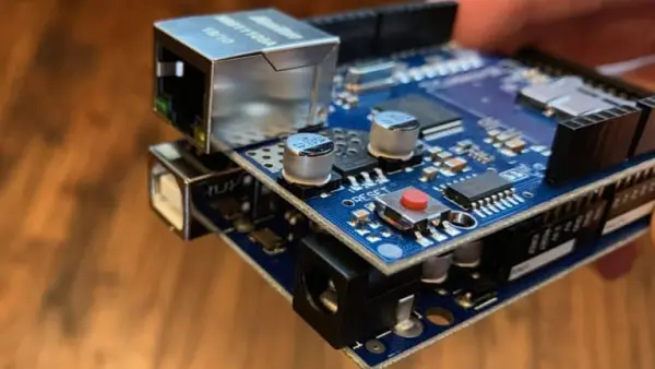
Before delving into controlling an Arduino via a web page, the initial step is to connect the Ethernet shield to the Arduino board. Aligning the shield’s pins and gently pressing it down achieves this connection. However, caution is warranted not to press it down too firmly, as this may cause the bottom of the Ethernet shield to make contact with the top of the USB port. Such contact could potentially lead to a short circuit. The specific shield utilized in this project is the Wiznet W5100 variant manufactured by Sunfounder, which is essentially a clone of the official Arduino W5100 shield.
Parts List for this Project
If you lack the necessary components for this list, here’s a basic parts inventory:
1. Arduino UNO or Arduino Mega 2560
2. W5100 Ethernet Shield
3. Blue LED
4. 10K Ohm Resistor
Wiring Diagram for Ethernet Controlled LED
Typically, I would utilize the built-in LED allocated to pin 13 for a project like this. However, employing that approach presents two significant challenges in this particular project. Firstly, the LED is obscured and difficult to discern due to the presence of the Ethernet Shield. Secondly, pin 13 is already allocated for use by the W5100 Ethernet shield. Consequently, for this project, I will instead connect a blue LED, accompanied by a 10K ohm resistor, to pin 2.
The wiring configuration should adhere to the following diagram:
That’s essentially the entirety of the wiring process. Connect the board to Ethernet and plug it into your PC via USB. Incorporate the provided code and upload it to the Arduino. Now, you’re set to commence controlling an Arduino through a web page!
You may find it necessary to modify the IP address (I’ve used 192.168.1.212) to align with your home network’s subnet. Apart from this adjustment, no other modifications are required.
// The Geek Pub - Controlling an Arduino Pin from a WebPage// Freely distributable with attribution and link to TheGeekPub.com#include "SPI.h"#include "Ethernet.h"byte mac[] = { 0xDE, 0xAD, 0xBE, 0xAD, 0xEE, 0xBE }; //physical mac addressbyte ip[] = { 192, 168, 1, 212 }; // IP address in LAN – need to change according to your Network addressbyte gateway[] = { 192, 168, 1, 1 }; // internet access via routerbyte subnet[] = { 255, 255, 255, 0 }; //subnet maskEthernetServer server(80); //server portString controlString; // Captures out URI querystring;;int blueLEDPin = 2; // pin where our blue LED is connectedvoid setup(){pinMode(blueLEDPin, OUTPUT); // change pin 2 to OUTPUT pin// Initialize the EthernetEthernet.begin(mac, ip, gateway, subnet);server.begin();}void loop(){// Create a client connectionEthernetClient client = server.available();if (client) {while (client.connected()) {if (client.available()) {char c = client.read();//read the HTTP requestif (controlString.length() < 100) {// write characters to stringcontrolString += c;}//if HTTP request has ended– 0x0D is Carriage Return \n ASCIIif (c == 0x0D) {client.println("HTTP/1.1 200 OK"); //send new pageclient.println("Content-Type: text/html");client.println();client.println("<html>");client.println("<head>");client.println("<title>The Geek Pub Arduino Ethernet Test Page</title>");client.println("</head>");client.println("<body>");client.println("<img src=\"https://cdn.thegeekpub.com/wp-content/uploads/2018/01/the-geek-pub-big-logo-new.jpg\") style=\"width: 55%; margin-left: auto; margin-right: auto; display: block;\" />");client.println("<h1 style=\"color: blue; font-family: arial; text-align: center;\">THE GEEK PUB ARDUINO ETHERNET TEST PAGE</h1>");client.println("<h2 style=\"color: green; font-family: arial; text-align: center;\">LED ON/OFF FROM WEBPAGE</h2>");client.println("<hr>");client.println("<h2 style=\"color: blue; font-family: arial; text-align: center;\"><a href=\"/?GPLED2ON\"\">Turn On The Blue LED</a> - <a href=\"/?GPLED2OFF\"\">Turn Off the Blue LED</a></h2>");client.println("</body>");client.println("</html>");delay(10);//stopping clientclient.stop();// control arduino pinif(controlString.indexOf("?GPLED2ON") > -1) //checks for LEDON{digitalWrite(blueLEDPin, HIGH); // set pin high}else{if(controlString.indexOf("?GPLED2OFF") > -1) //checks for LEDOFF{digitalWrite(blueLEDPin, LOW); // set pin low}}//clearing string for next readcontrolString="";}}}}}Understanding the Ethernet Shield Web Page Sketch
#include "SPI.h"#include "Ethernet.h"byte mac[] = { 0xDE, 0xAD, 0xBE, 0xAD, 0xEE, 0xBE };byte ip[] = { 192, 168, 1, 212 };byte gateway[] = { 192, 168, 1, 1 };byte subnet[] = { 255, 255, 255, 0 };EthernetServer server(80);int blueLEDPin = 2;
pinMode(blueLEDPin, OUTPUT);Ethernet.begin(mac, ip, gateway, subnet);server.begin();In this concluding section, I won’t delve deeply into the process of constructing an HTML page destined for your browser. The basics of HTML lie outside the purview of this tutorial.
Essentially, the loop routine is primed to await a command. Upon receiving one, it employs the digitalWrite function to alter the state of the blue LED.
Other Ideas for Controlling an Arduino from a Web Page
Apart from merely illuminating an LED, the versatility of this technology extends to a multitude of applications. Utilizing a relay enables control over devices requiring higher voltage or current, surpassing the Arduino’s capabilities. For instance, one could regulate a pump within a well house. Furthermore, integrating lighting systems facilitates home automation, while managing dust collection systems in woodworking shops. The potential applications for this technology are virtually limitless, spanning across various domains.
Wi-Fi Shield
Although we discussed the Ethernet shield in this article, it’s worth mentioning that Wi-Fi shields are also accessible for remotely controlling an Arduino via a web page wirelessly. This functionality is particularly advantageous for battery-powered projects such as robots and vehicles.
- How do I connect the Ethernet shield to the Arduino?
Align the shield pins with the Arduino headers and gently press the shield down, taking care not to press too hard so the shield bottom does not contact the USB port. - Which pin is the blue LED connected to in this project?
The blue LED is connected to digital pin 2 with a 10K ohm resistor. - What libraries are required for the Ethernet web server sketch?
The sketch requires the SPI library and the Ethernet library. - How do I change the Arduino IP address for my network?
Edit the ip[] array in the sketch to match your home network subnet (the example uses 192.168.1.212). - How does the web page turn the LED on and off?
The page sends URI query strings ?GPLED2ON to turn the LED on and ?GPLED2OFF to turn it off, which the sketch detects in controlString and uses digitalWrite to change the pin state. - What port does the Arduino web server use?
The server uses port 80 as defined by EthernetServer server(80). - How can I verify the Arduino is connected to the network?
Open a command prompt and ping the Arduino IP (for example ping 192.168.1.212) to confirm network connectivity. - Can I control devices other than an LED with this method?
Yes; the article suggests using relays to control higher voltage or current devices, lighting systems, pumps, or other automation tasks. - Is wireless control possible instead of Ethernet?
Yes; the article notes Wi-Fi shields are available for wireless web control, useful for battery-powered projects.