
Summary of Real Time Clock On 20×4 I2C LCD Display with Arduino
This article details a project to display a real-time clock and date on an Arduino using an I2C 20×4 character LCD and a DS3231 RTC module. The setup utilizes the I2C interface, requiring only two wires for the LCD connection. The tutorial covers hardware connections, component specifications like voltage and address, and the functionality of the RTC in maintaining accurate time with backup battery support.
Parts used in the Real-Time Clock Display Project:
- Arduino UNO
- I2C 20×4 Character LCD Display
- DS3231 Real-Time Clock Module
Introduction
Sometimes it may be necessary to use a display while making a hardware project, but the size and the type of the display may vary according to the application. In a previous project, we used a 0.96″ I2C OLED display, and in this project we will have an I2C 20×4 character display.
Project Parts
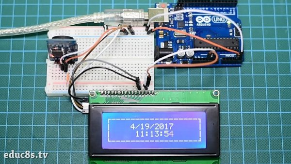
This tutorial will describe how to use 20 x 4 LCD display with Arduino to print a real-time clock and date.
This liquid crystal display has 4 lines, 20 character in each line and cannot be used to display graphics. The main feature of this display that it uses I2C interface, which means that you will need only two wires to connect with Arduino. At the back side of the screen there is a small PCB soldered in the display, this circuit is a serial LCD 20 x 4 module and it also has a small trimpot to adjust the contrast of the LCD.
Display’s backlight is blue and the text is white. It is fully compatible with Arduino and has 5V input voltage. Its I2C address could be 0x27 or 0x3F. You can get it for about $7 from Bangood store.
DS3231 is a low-cost, accurate I2C real-time clock (RTC), with an integrated temperature-compensated crystal oscillator (TCXO) and crystal. The device incorporates a battery input, so that if power is disconnected it maintains accurate time.
RTC maintains seconds, minutes, hours, day, date, month, and year information. Less than 31 days of the month, the end date will be automatically adjusted, including corrections for leap year. The clock operates in either the 24 hours or band / AM / PM indication of the 12-hour format. Provides two configurable alarm clock and a calendar can be set to a square wave output. Address and data are transferred serially through an I2C bidirectional bus.
This RTC module operates at input voltage range between 3.3V and 5.5V, so it can be connected with 3.3V or 5V pins. It is available on Banggood store for about $2.
Connecting the LCD with Arduino UNO
At first we will connect the LCD with Arduino to display some text and to learn how it works.
Read more: Real Time Clock On 20×4 I2C LCD Display with Arduino
- How many wires are needed to connect the LCD to Arduino?
Only two wires are needed because the display uses the I2C interface. - What is the input voltage requirement for the LCD display?
The display has a 5V input voltage requirement. - Can this LCD display graphics?
No, the liquid crystal display cannot be used to display graphics as it only supports text. - What is the function of the trimpot on the back of the screen?
The small trimpot is used to adjust the contrast of the LCD. - Does the DS3231 RTC maintain time if power is disconnected?
Yes, the device incorporates a battery input so it maintains accurate time when power is disconnected. - What time formats does the RTC module support?
The clock operates in either the 24 hours or 12-hour format with AM/PM indication. - What is the operating voltage range for the RTC module?
The module operates at an input voltage range between 3.3V and 5.5V. - Are there configurable alarms available on the RTC module?
Yes, the module provides two configurable alarm clocks.
