Summary of Reaction Speed Timer
This article describes building a reaction speed timer using a PIC16F1823 microcontroller. Replacing original Nixie tubes with 7-segment LED displays, the device starts timing on a button press, signals readiness with an 'H', and displays results upon release. It features error handling for holding the button too long. The project uses a shift register for display control to save microcontroller pins and runs without external libraries.
Parts used in the Reaction Speed Timer:
- PIC microcontroller 16F1823
- 74HC595 shift register
- 5 * 7-Segment LED Display (common cathode)
- 5 * BC548 transistor
- Resistors (1x 33k, 8x 220 Ohm, 5x 1k)
- 100 nF capacitor
- 1 push button
Many, many years ago – when I was young – I visited the Evoluon in Eindhoven, The Netherlands. At that time it had all kind of technical stuff you could see and you could play with. Nowadays it does no longer exists in that form since the Evoluon has changed into a conference center.
One of the items you could play with at the Evoluon was a reaction speed timer which was built with discrete components using Nixie Tubes to show your reaction speed. In order to start this timer you had to press a button and after a random time the display showed a running counter. When the counter started running you had to release the button as soon as possible. The counting then stopped and the display showed your reaction speed.
Nowadays we can make the same thing more easily using a microcontroller which I did for this Instructable. In this case the Nixie Tubes are replaced by 7-segment LED displays. The original reaction timer in the Evoluon showed the timer running when the random timeout had passed – and you had to release the push button – but due to the fact that it takes too much CPU cycles to continuously update the display with the actual timer value, I decided to only show ‘H’ on the middle display to indicate that the random timeout has passed. The actual reaction time is then shown after the push button is released.
The operation is as follows:
- One push button is used to start and stop the reaction speed timer
- When the push button is pressed, the display shows ‘-‘ on all displays
- After a random time, the middle display will show ‘H’ after which the push button has to be released as fast as possible
- After releasing the push button, the display will show your reaction time
- If the push button is pressed for too long, all displays will show ‘H’ after releasing the push button
As always I used a PIC microcontroller and created all software without using any specific libraries. Arduino fans can use of course do the same.
Step 1: Required Components and Building the Circuit
You need to have the following components for this project:
- PIC microcontroller 16F1823
- 74HC595 shift register
- 5 * 7-Segment LED Display, command cathode
- 5 * BC548 transistor
- 1 * 33k, 8 * 220 Ohm, 5 * 1k resistors
- 100 nF capacitor
- 1 push button
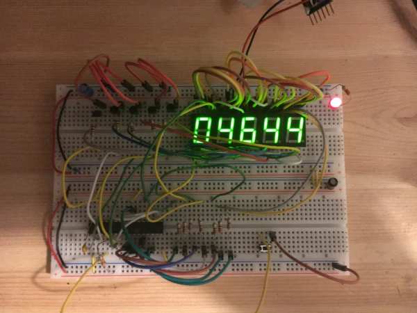
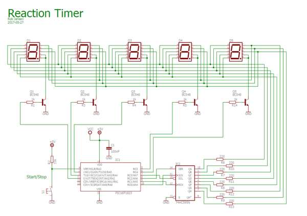
See the schematic diagram on how to connect the components. I only built this Instructable on a prototype board but is can easily be made on a breadboard.
Step 2: The Software and Operation
As already mentioned, the software is written for a PIC16F1823. It was written in JAL. Since I did not use any specific libraries the total code size is 587 bytes which fits easily in the 2k program flash memory this specific controller has.
The software performs the following main tasks:
- Start measuring the reaction time after a random timeout when pressing the push button. For this it uses an internal timer that runs at a frequency of about 15 kHz
- Show the reaction time on the 7-segment LED displays. These displays are multiplexed in software and are controlled via the 74HC595 shift register since there were insufficient pins remaining on the controller to control the 7-segments directly from the IO pins of the PIC. In order to control the shift register, the SPI interface of the PIC is used. This interface can be programmed in such a way that it directly controls the clock and data input of the shift register. The multiplexing frequency of the display is about 100 Hz
The PIC controller runs on an internal clock with a frequency of 500 kHz. A low internal clock was chosen as to prevent that the timer that measures the reaction time would overflow too quickly. The source file and the Intel Hex file of this program is attached.
The video shows the reaction timer in action where the push button is pressed and released 3 times after which it shows the reaction time. This also shows the random start time. The fourth time the push button pressed to long which results in showing 5 times ‘H’ on the display. This indicates that the push button was not released before an overflow of the timer which happens after about 4,3 seconds.
Have fun building your own project and looking forward to your reactions and the person with the lowest reaction time.
Source: Reaction Speed Timer
- How does the user start the reaction timer?
The user must press a single push button to initiate the random timeout sequence. - What happens when the random timeout passes?
The middle display shows an H to indicate the timer has started and the button should be released. - Can Arduino users build this project?
Yes, although the author used a PIC, the text states that Arduino fans can do the same. - Why is a 74HC595 shift register used?
It is used because there were insufficient IO pins on the controller to drive the 7-segments directly. - What indicates if the button was held too long?
All five displays will show H after releasing the button if it was pressed for more than about 4.3 seconds. - What frequency does the internal timer run at?
The internal timer measures reaction time at a frequency of about 15 kHz. - Does the project require specific software libraries?
No, the software was created without any specific libraries to keep the code size small. - How are the 7-segment displays controlled?
The displays are multiplexed in software at about 100 Hz via the SPI interface of the PIC.