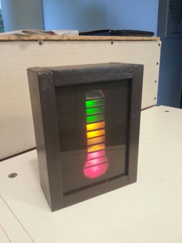
Harsh new rules at work getting you down? Overtime sucking the life out of you? Or maybe things are great, either way now you can show your co-workers and management exactly how you feel about your job without a single meeting, memo, or team bonding exercise. This is the Quality of Life Meter. Boss take credit for your hard work? Turn it down. Get a bigger bonus than expected? Turn it up.
 There is no exact formula for the Quality of Life Meter, the whole idea is that it’s a personal thing. That being said on my project we use it as a measure of the groups level. Things like taking a day off, long weekends, cancelled meetings, and getting critical data on time make the meter go up while overtime, useless meetings, server crashes, and management trying to dictate our quality of life make it go down. It’s kind of a gut thing and you’ll have to decide for your self exactly what factors into moving your meter.
I won’t bore you with the story of how this came about but I will be clear that in my work place this is clearly a joke and everyone knows it. If you just show up with this one day and set it low feelings may be hurt and people may take it personally. I’m not saying I’m against using this as a tool to vent your frustrations but just make sure your intentions are clear, joke or otherwise.
Of course Quality of Life isn’t the only thing you can use this for, that’s the biggest reason there isn’t a label directly on the box (at work there is a sign over it but there’s a strict no photo rule so I can’t show it). It could jazz up a fundraiser, track your exercise, or help you save up for a trip. The Arduino that powers my design is far from working at capacity so there is the possibility for expanding the meter by adding sensors that can directly control the output value or adding WiFi or Bluetooth connectivity allowing your phone or computer to influence the output.
As always, feel free to ask any questions in the comments or via PM and if you make one, or a variation, I love to see pictures.
Step 1: Materials & Tools
Materials
- Small Glass/Plastic Pane – Any material that is clear and stiff will work. Glass or plexiglass are the most obvious solutions.
- Sheet Wood – The type of wood is mostly irrelevant as is the thickness, although I wouldn’t go much thinner than 3/8″ or 1/4″. I used some 3/4″ strips that were packed with some toe kicks from IKEA.
- Cardboard/Plastic Sheet – Any thin, presentable looking material will work, even sheet metals.
- Small Knob – This needs to fit your pot and be long enough to make it through the wall of your enclosure. In my build I improvised and used an internally threaded spacer as a knob.
- Screws – Small screws to attach the back sheet to the wood enclosure.
- Frosting Spray Paint; ($4, Lowes) – If you can find a pre-frosted pane then this is unnecessary.
- Regular Spray Paint – I used the same color for the enclosure as well as for the blackout on the pane.
- Wood Filler – When working with particle board (of all varieties) or ply woods using wood filler on the cut edges helps give a uniform texture and look after painting.
- Wood Glue – Holds it all together.
Circuit Kit
- 2x Small Perfboards
- 1x Arduino Uno
- 1x 6xAA Battery Holder
- 12x 220 Ohm Resistors
- 1x Red Blinking LED
- 3x Red LEDs
- 4x Yellow LEDs
- 3x Green LEDs
- 1x Green Blinking LED
- 2x 74HC595 Shift Registers
- 2x 16 pin IC Sockets
- 1x SPST Switch
- 1x Potentiometer – I honestly don’t know the size I used as mine was salvaged. It just needs to have even output across a range of 0-3V.
- Wires
- Batteries
Tools
- Table or Circular Saw – A table saw is best but you can make due with a circular or even a hand saw if one isn’t readily available.
- Sandpaper
- Clamps
- Masking Tape
- Soldering Equipment
- Drill & Bits
- Utility Knife / Scissors
Step 2: Circuit Design
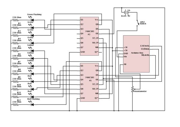
The circuit is relatively straight forward even though the circuit diagram looks pretty messy, there are a lot of connections. Initially I was trying for a 2×6 multiplexed array using a single 595 chip. This turned out to be very hard to program and it may be impossible as I tried several things that I really felt should have worked, at least partially, but got zero results. It worked fine on LEDS 2-11 but the issues start cropping up when you try and integrate flashing LEDs into the circuit. Physical flashing LEDs, like I utilize in the current circuit, don’t work because the current is cycling on/off and the LED never has time to get to the off phase, making them stay on constantly. Software solutions designed to make a standard LED flash resulted in similar abject failures. If anyone can whip together a working proof of concept I’d be very interested to see it. After several frustrating weeks spent bug hunting, troubleshooting, and reconfiguring I realized I had a second 595 so I moved to a new circuit with the two 595’s daisy chained to get the required number of outputs.
The 74HC595’s are serial-in-parallel-out shift registers. This means you can use three pins on your microcontroller to send the bytes of data serially (one bit after another) to the 595 which then applies each bit to different output pins and then outputs those bits in parallel (all at once). When you daisy chain 595’s you can now send two bytes of data and the first 595 then passes the first byte onto the second 595 and they both execute all 16 bits at once.
*Enough faffing about though, lets break down this circuit. Starting with the Arduino, we are using 3 digital pins to control the 595’s. Pin 8 is the latch pin which holds the outputs steady while you write new data and is attached to pin 5 on both 595’s. Pin 11 is used to transmit the serial data and is attached to pin 3 on the FIRST 595 ONLY. Pin 12 is the clock which pulses to send each bit and it’s attached to pin 6 on both 595’s.
The 5V output pin is attached to pins 1 and 7 on both 595’s. The GND pin grounds all five “chunks” of the circuit.
*The potentiometer takes 3.3V from the Arduino and runs back to the Arduino ground. The sweep, or output, is connected to the first analog pin on the Arduino, A0. I don’t know the value of the pot as it’s a salvage but it is pretty small in size and made out of plastic so it can’t be anything crazy.
*The power source is 6 AA batteries, providing ~9V, in a holder that uses a 9V battery clip as leads. The positive terminals pass through a push button SPST to the Vin pin on the Arduino. The plan is to use rechargeable batteries to cut running costs.
*On the 595’s the pins I haven’t addressed are 3, 4, 8, and the outputs. Pin 3 on #1 connects to the Arduino, as discussed above, but on #2 it ties to pin 8 on the first 595. Pin 8 is left unconnected on #2. On both 595’s pin 4 connects to GND. The outputs, labeled as Q’s, are pretty straight forward. starting with Q0 on #1 and the red flashing LED and ending with the green flashing LED attached to Q3 on #2.
*The LED array is simply a parallel array, one LED and resistor per row. All the resistors tie to the common ground. The size of the resistor needed depends on the specs of your specific LEDs. Use R = V / I, where R is the size of resistor needed, V is the voltage passing through the LED (5V if you use Arduino), and I is the acceptable current for the LEDs. 220 Ohm resistors will work well for most standard 5mm LEDs.
Step 3: Enclosure Design
The enclosure is a simple wooden “picture frame” with a glass/plastic face and a cardboard back. The size of the enclosure was determined by the glass pane I found and the depth was set by the width of the scrap wood was making it with. The window is held in place by a groove cut into the frame and the backing is simply screwed into place.
To create the thermometer outline I simply scaled free a clip art picture to fit on the window. Before you start finalizing your circuit and soldering it into place you need to know the final size of the image so that you can get the spacing of the LEDs correct.
For more detail: Quality of Life Mete