Summary of My Ninth Project: Robot Arm with Joystick Shield using Arduino
This project enables precise robot arm control via a joystick shield compatible with Arduino. The setup integrates a 16-channel servo controller, nRF24L01 wireless module, Bluetooth module, and Nokia 5110 LCD for enhanced functionality. Powered by a 7.4V Li-Po battery and regulated voltage, the system offers a convenient and fun way to manipulate robotic arms wirelessly or locally.
Parts used in the Robot Arm with Joystick Shield:
- Joystick Shield
- Robot Arm Set
- 16-Channel Servo Controller
- Arduino UNO
- Buck Regulator with Indicator
- 7.4V Li-Po Battery
- Charger
- JST female connector
- Standoff
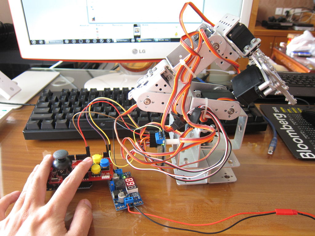
Although it is great controlling the robot arm with computer or mobile phone, I think using joystick is also cool, so I’ve bought a joystick shield and make a new project. This joystick shield is compatible with Arduino. It also support Nokia 5110 LCD module, nRF24L01 wireless module and Bluetooth module. It should be fun and convenient for various projects. : )
Step 1: Parts
7.4V Li-Po Battery
Charger
JST female connector
Standoff
Step 2: Assembly
For assembling Robot Arm Set you can follow the manual downloaded from the link. You can also refer to my seventh project. For Joystick Shield it is very simple: There are pin headers that are compatible with Arduino, just plug this shield to the pins on Arduino UNO / MEGA and that’s it.
Step 3: Wiring
This is a continuation of the seventh project and the wiring between robot arm and servo controller is just the same.
For servo cable:
Brown = GND
Red = +
Orange = Signal
From servos to servo controller:
Servo at the base > S1
……
Servo at the claw > S6
Use extension wires if the servo cable is not long enough. Make sure all the cables are in correct direction.
For Battery:
Red wire of 7.4V Li-Po Battery > IN + of buck regulator
Black wire of 7.4V Li-Po Battery > IN – of buck regulator
For Buck Regulator
OUT + > VS of the blue terminal block on servo controller
OUT – > GND of the blue terminal block on servo controller
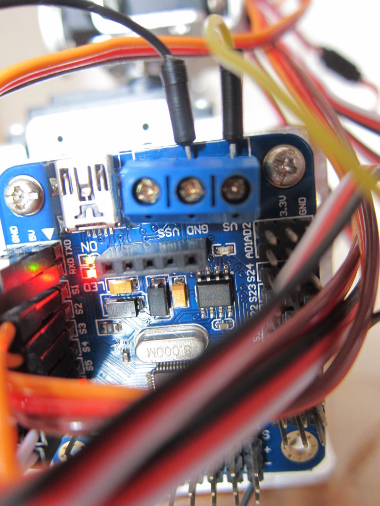
From servo controller to Joystick Shield
Pin GND > – on Joystick Shield
Pin 5V > + on Joystick Shield
RXD > Pin 0 on Joystick Shield
TXD > Pin 1 on Joystick Shield
For more detail: My Ninth Project: Robot Arm with Joystick Shield using Arduino
- What components are compatible with the Joystick Shield?
The shield supports the Nokia 5110 LCD module, nRF24L01 wireless module, and Bluetooth module. - How do you assemble the Joystick Shield?
You simply plug the shield into the pin headers on an Arduino UNO or MEGA board. - What are the color codes for the servo cables?
Brown is GND, Red is positive voltage, and Orange is the signal line. - Which pins connect the servo controller to the Joystick Shield?
Connect GND to negative, 5V to positive, RXD to Pin 0, and TXD to Pin 1 on the shield. - How is the power supply wired for the system?
The 7.4V Li-Po battery connects to the buck regulator inputs, which then output to the servo controller terminal block. - Can I use extension wires for the servos?
Yes, use extension wires if the original servo cables are not long enough. - Does this project replace previous versions of the robot arm?
This is a continuation of a seventh project with identical wiring between the robot arm and servo controller.